Switched capacitor type d/a converter

a technology of d/a converter and switch capacitor, which is applied in the direction of pulse manipulation, pulse technique, instruments, etc., can solve the problems of deterioration of power supply rejection ratio (psrr) of d/a converter and sound quality deterioration, so as to suppress the fluctuation of on resistance of each switch, improve psrr, and suppress the effect of deterioration of psrr

Inactive Publication Date: 2012-01-19
ROHM CO LTD
View PDF12 Cites 3 Cited by
  • Summary
  • Abstract
  • Description
  • Claims
  • Application Information

AI Technical Summary

Benefits of technology

[0020]Switching noise is superimposed on the output voltage of the DC / DC converter. However, by employing a P-channel MOSFET as such a switch, such an arrangement provides an advantage of the PSRR characteristics not being subjected to the effects of such switching noise.
[0022]The linear regulator is configured to generate a voltage according to the reference voltage received from the band gap reference circuit. Accordingly, the output voltage is provided with a high PSRR. Accordingly, the high level voltage of the gate signal output from each of the first and second inverters is provided with a high PSRR. Thus, such an arrangement is capable of suppressing fluctuation in the on resistance of each switch even if an N-channel MOSFET is employed as such a switch. Thus, such an arrangement is capable of suppressing deterioration in the PSRR of the D / A converter, or provides an improved PSRR.
[0024]Such an embodiment is capable of suppressing fluctuation in the on resistance of each of the P-channel MOSFETs and the N-channel MOSFETs. Thus, such an arrangement is capable of suppressing deterioration in PSRR of the D / A converter, or provides an improved PSRR.
[0026]With the D / A converter according to any one of the aforementioned embodiments, such an arrangement provides high-quality audio signal processing.

Problems solved by technology

That is to say, if noise is superimposed on the power supply voltage Vdd, the on resistance of each switch fluctuates, leading to a problem of deterioration in the power supply rejection ratio (PSRR) of the D / A converter.
If such a D / A converter is used to perform audio signal processing, such an arrangement leads to a problem of deterioration in the sound quality.

Method used


Image

  • Switched capacitor type d/a converter
  • Switched capacitor type d/a converter
  • Switched capacitor type d/a converter

Examples


first embodiment

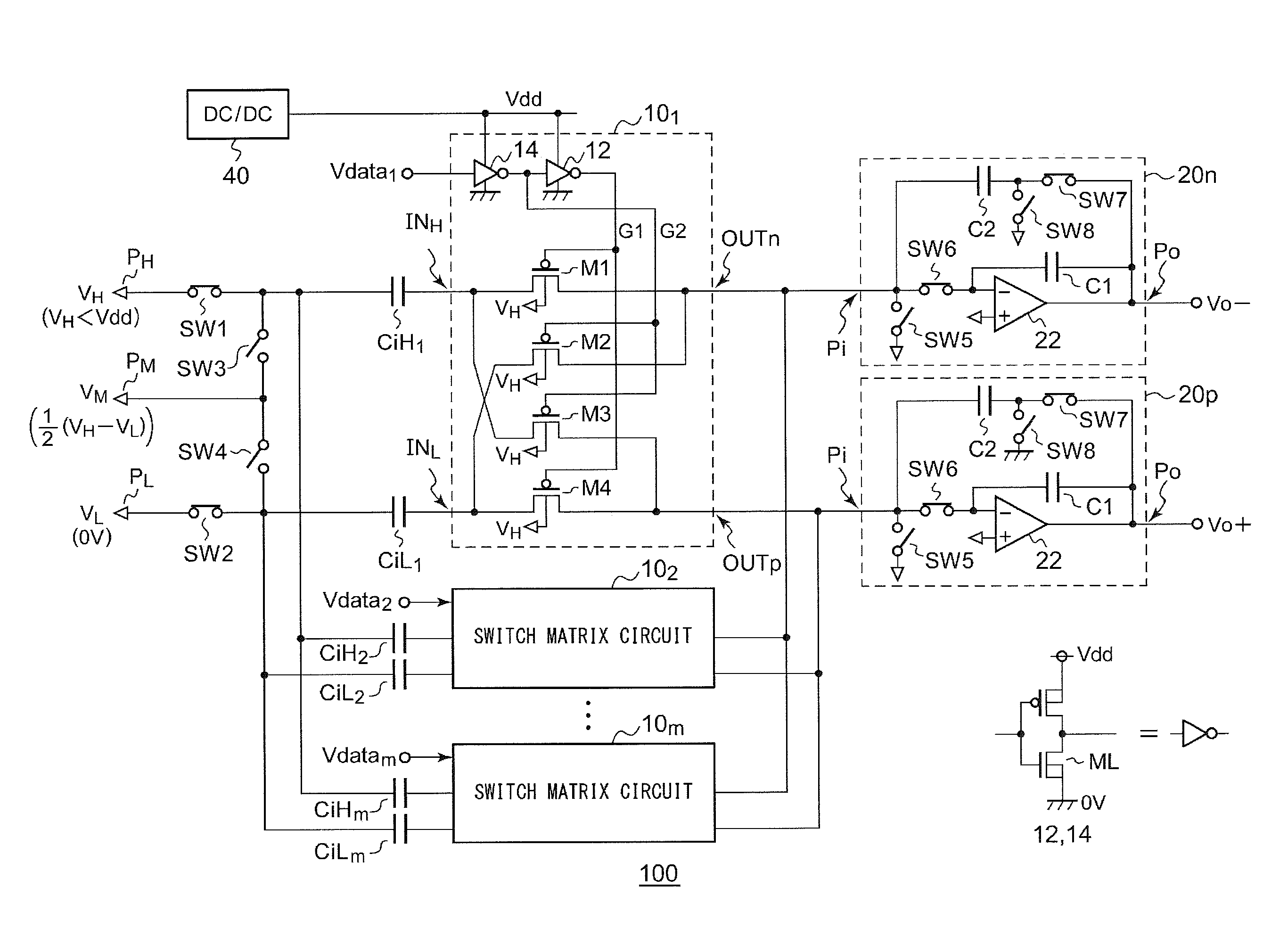
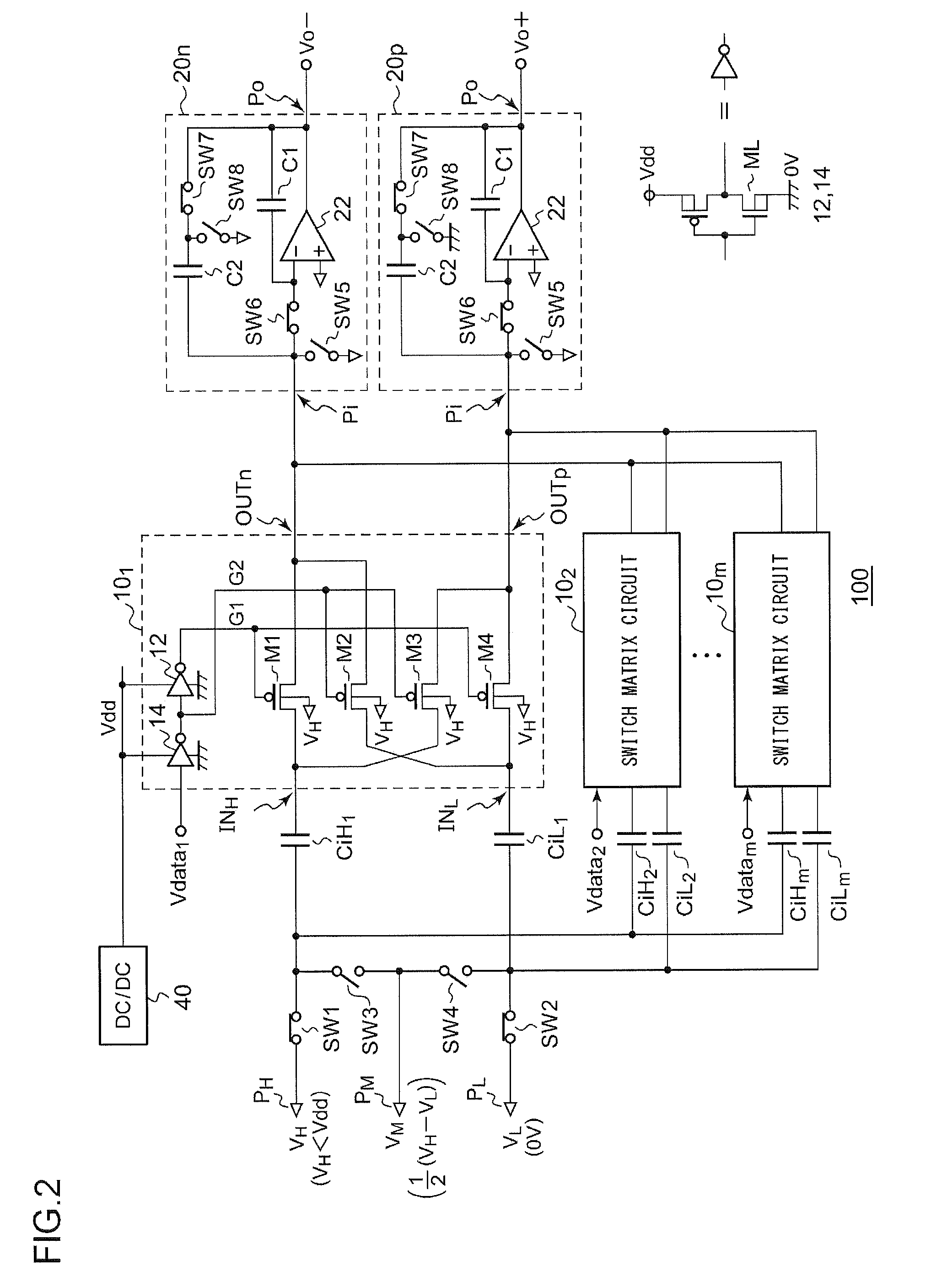
[0038]FIG. 2 is a circuit diagram which shows a configuration of a switched capacitor type D / A converter 100 according to a first embodiment.

[0039]The D / A converter 100 receives m-bit (m represents an integer) input data Vdata1 through Vdatam, and outputs a differential analog signal that corresponds to the value of the input data thus received. Examples of such input data include a digital audio signal.

[0040]The D / A converter 100 includes m switch circuits 101 through 10m provided to the respective bits Vdata1 through Vdatam of the input data, m input capacitor pairs (CiH / CiL)1 through (CiH / CiL)m provided to the respective bits Vdata1 through Vdatam, switches SW1 through SW4, a first calculation unit 20p, and a second calculation unit 20n.

[0041]An upper reference voltage VH, a middle reference voltage VM, and a lower reference voltage VL are supplied to the respective terminals PH, PM, and PL of the D / A converter 100.

[0042]The switch circuits 101 through 10m are each configured in...

second embodiment

[0064]Description will be made in the second embodiment regarding a technique for providing an improved PSRR by means of an approach that differs from that used in the first embodiment.

[0065]FIG. 3 is a circuit diagram which shows a configuration of a power supply unit of a D / A converter 100a according to a second embodiment. In the second embodiment, switches M1 through M4, which compose a switch circuit 10 of the D / A converter 100a, are each configured as an N-channel MOSFET.

[0066]A power supply unit of the D / A converter 100a includes a DC / DC converter 40, a band gap reference circuit 30, a start-up circuit 32, a first linear regulator 34, and a second linear regulator 36.

[0067]The DC / DC converter 40 is configured to receive an input voltage on the order of 3 V, and converts the input voltage thus received into a power supply voltage Vdd on the order of 1.8 V. The input voltage may be supplied as a battery voltage, for example.

[0068]The band gap reference circuit 30 generates a re...

third embodiment

[0074]A third embodiment can be understood as being a combination of the first and second embodiments. FIG. 4 is a circuit diagram showing a part of a configuration of a D / A converter 100b according to the third embodiment. A power supply unit of the D / A converter 100b should be configured in the same way as the power supply unit shown in FIG. 3. Accordingly, the power supply unit of the D / A converter 100b is not shown in the drawing.

[0075]In the D / A converter 100b, each switch that is a component of a switch circuit 10b is configured as a transfer gate TG. The transfer gate TG includes a P-channel MOSFET and an N-channel MOSFET. The second power supply voltage Vdd′ is supplied to the upper power supply terminal of each of a first inverter 12 and the second inverter 14. The ground voltage 0 V is supplied to the lower power supply terminal of each of the first inverter 12 and the second inverter 14.

[0076]With such a third embodiment, such an arrangement provides a high PSRR while pro...


PUM


Abstract

A switched capacitor type D / A converter receives m-bit (m represents an integer) input data, and outputs an analog signal that corresponds to the input data value. Switch circuits are provided to respective bits of the input data, and are classified into two groups: a first group configured to turn on when the corresponding input data bit is 1, and to turn off when the corresponding input data bit is 0; and a second group configured to turn on when the corresponding input data bit is 0, and to turn off when the corresponding input data bit is 1. Each switch of the first and second switch groups is configured as a P-channel MOSFET (Metal Oxide Semiconductor Field Effect Transistor). The ground voltage 0 V is applied to the lower power supply terminal of each of the first and second inverters configured to supply a gate signal to each switch.

Description

BACKGROUND OF THE INVENTION[0001]1. Field of the Invention[0002]The present invention relates to a switched capacitor type D / A converter.[0003]2. Description of the Related Art[0004]As a D / A converter configured to convert a digital signal into an analog signal, a switched capacitor type D / A converter is known. Such a switched capacitor type D / A converter receives N-bit data, and outputs an analog signal having a voltage level that corresponds to the data thus received.[0005]The D / A converter includes a switch configured to be controlled to turn on / off in synchronization with a clock signal, and switches each configured to be controlled to turn on / off according to a corresponding bit of digital data. As disclosed in Patent document 2, typical switched capacitor type D / A converters employ, as such a switch, an N-channel MOSFET (Metal Oxide Semiconductor Field Effect Transistor) or a transfer gate using such an N-channel MOSFET.[Related Art Documents][Patent Documents][Patent Document...

Claims


Application Information

Patent Timeline
IPC IPC(8): H03M1/66
CPCH03M1/0682H03M1/804H03M1/0845
Inventor NAKAMURA, KEI
Owner ROHM CO LTD
Why Eureka
Try Eureka