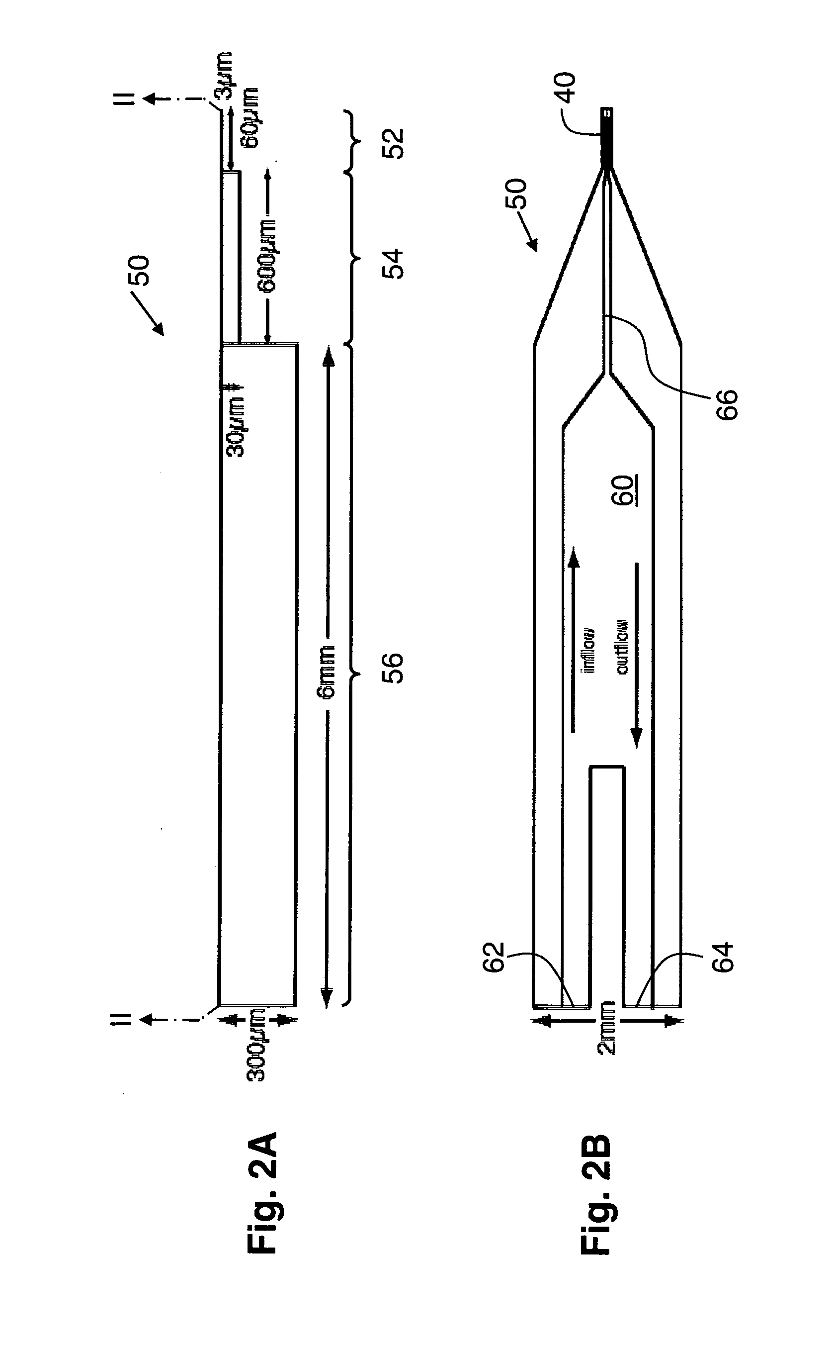
However, the narrowing of the tip end both decreases the conductance of the end portion of the conductive path markedly and impedes the
insertion of the wire toward the tip end in a drawn glass pipette, limiting the degree to which the
total resistance of the path can be reduced.
The minute currents involved and the relatively high source impedance of the electrical path from the
amplifier into the cell (i.e. ‘
input resistance’) present a significant impediment to obtaining reliable
electrical measurements in the face of inevitable electrical
noise.
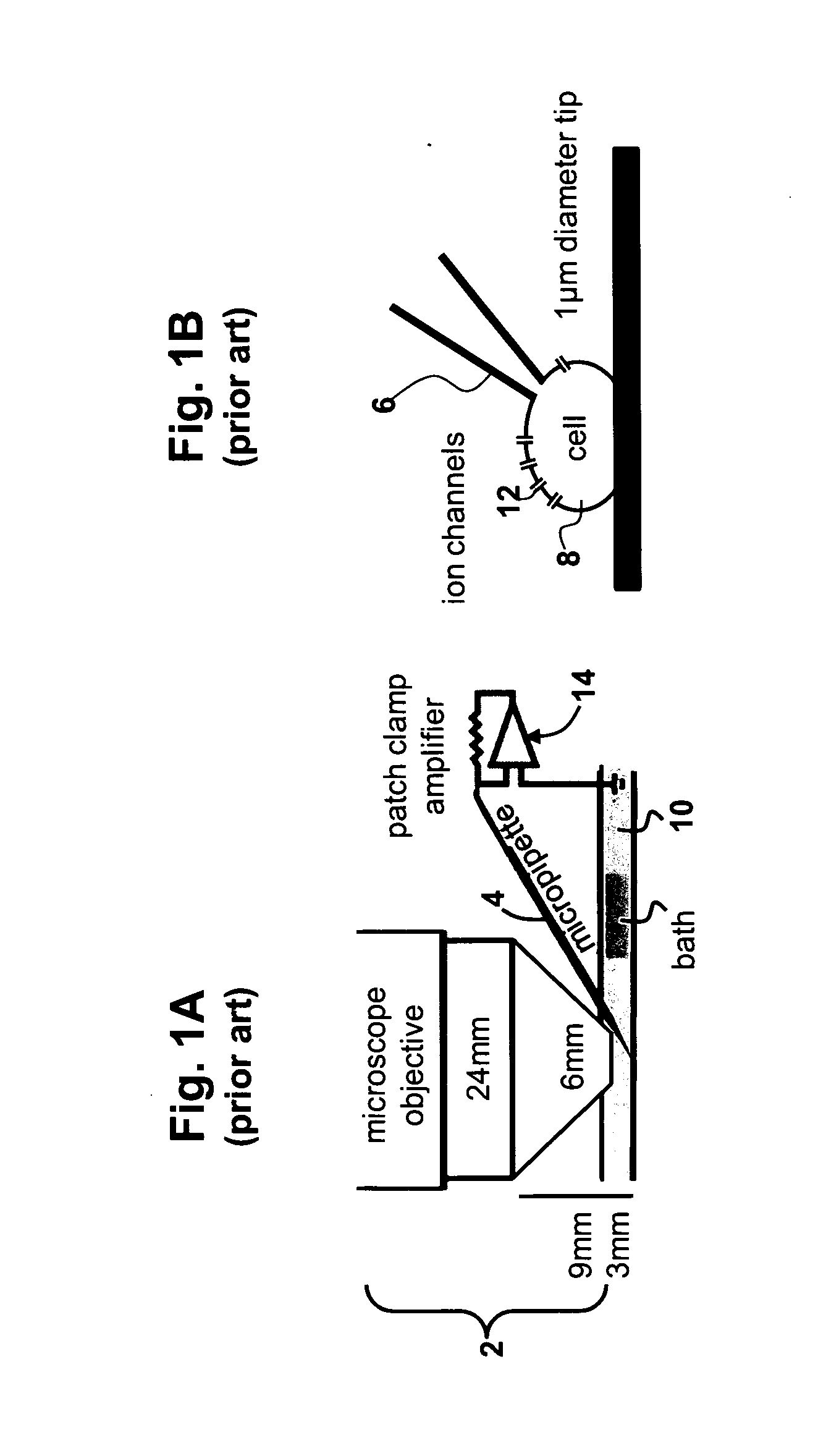
Despite the advances that have come from the
patch clamp technique, the glass micropipettes conventionally used have inherent characteristics that limit the technique's applicability and the
research data that it can produce.
Many of these limitations directly arise from mechanical and practical attributes of conventional pipettes.
The production of micropipettes by drawing capillary tubes is notoriously difficult and time-consuming.
These steps require significant manual dexterity and are prone to error, as the wire is fragile and can be bent or contaminated by oils or other residues.
After being used, a pipette is contaminated and must be dismounted and discarded, since its tiny size and
fragility inhibit effective cleaning.
The individual manufacture required and low yield of the drawing process present further serious complications.
In addition, the reproducibility of tip geometry from pipette to pipette is relatively poor.
In addition to problems in manufacture, conventional pipettes have several severe functional limitations.
This adds uncertainty to the measurement, and in some cases makes the desired measurement impossible.
The
dilution also eventually kills the cell, limiting the time over which measurements can be taken.
Although several techniques have been developed to mitigate these problems, these techniques add
much difficulty and complexity to the process, have their own inherent problems, and as a result are only rarely practiced.
In addition to the manufacturing and functional problems listed above, traditional patch clamp is also both expensive and time-consuming, as it requires a
microscope, micro-manipulators, and highly trained personnel to assemble, operate and maintain the apparatus, including pulling individual pipettes and adjusting the pipette puller to compensate for changes in
humidity, temperature and normal
wear and tear.
Because of the manual dexterity needed to manufacture, fill,
mount and maneuver pipettes, these steps cannot be easily automated, limiting the overall productivity of a patch clamp apparatus and the
scalability of the method.
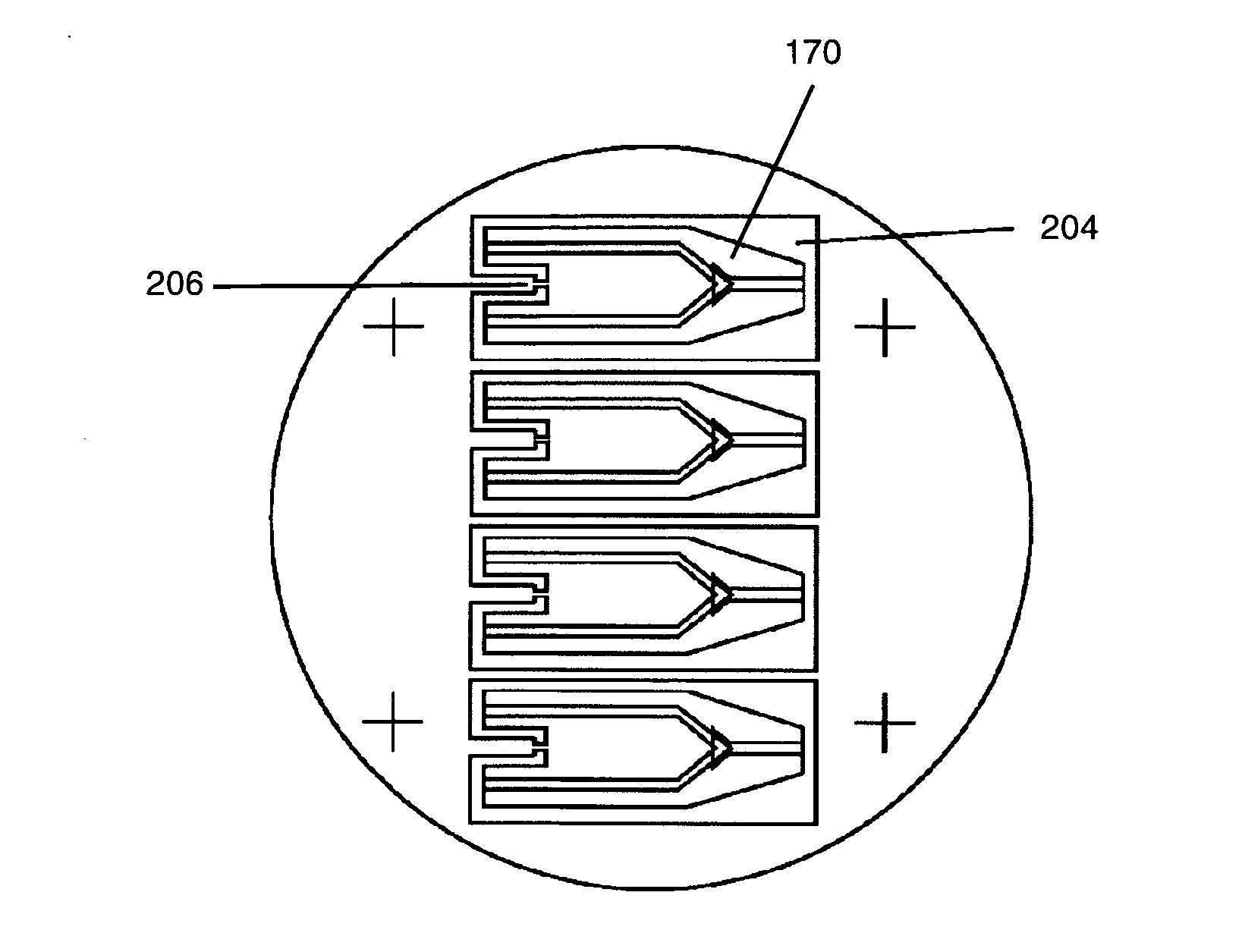
However, such structures are not controllable, in that particular cells cannot be identified and selectively clamped.
Instead, the technique relies on the random attachment of multiple cells in a bath, limiting a researcher's ability to control the data collection.
In addition, many embodiments of this technique do not form gigaseals reliably or at all, reducing the quality of the recording and limiting its usefulness for government approval.
Another major problem is the planar patch clamp technique is limited to studying individual cells that are dissociated in a carrier liquid and removed from their original anatomical position and function.
Such information inherently cannot be obtained by studying isolated cells.

