Hall-current ion source with improved ion beam energy distribution

a broad-beam ion source and hall-current technology, applied in the direction of light sources, electric discharge tubes, electrical apparatus, etc., can solve the problems of not being very practical, not working well at high discharge currents, and substantial erosion, so as to eliminate ion beam contamination and effectively neutralize and ion beam

Inactive Publication Date: 2012-02-02
KLYUEV EVGENY VITALEVICH +1
View PDF9 Cites 20 Cited by
  • Summary
  • Abstract
  • Description
  • Claims
  • Application Information

AI Technical Summary

Benefits of technology

[0024]Still another object of the present invention is to utilize a placement of a Hot Filament on a top of an ion source exit flange outside an ion beam flow, and Hot Filament's heated wire is covered with a specially designed shield that protects a target and a substrate from a Hot Filament radiation and eliminates an ion beam contamination with a Hot Filament wire material, and still effectively neutralizes and ion beam.

Problems solved by technology

Such a design was tested and worked well at not high discharge currents, and it was not very practical, because to substitute a Hot Filament, which usually has to be done after about 10-20 hours or less of operation, it was necessary to disassemble the whole ion source.
This portion of ion beam applied to the reflector produces substantial erosion sputtering reflector's material and contaminating an ion beam.
As one can see, it is not easy to characterize a mean ion energy of this ion source, especially in a low energy distribution.
However, this design has a substantial disadvantage: anode in the conditions of ion source operation vacuum, when a mean free path of working gas molecules is substantially longer than a discharge channel width, can not be properly cooled through an intermediate dielectric or insulator, because with a long mean free path of working gas molecules there is no convective heat transfer leading to cooling, there is only a radiation cooling, and anode becomes overheated especially at high applied powers.
Also, because a working gas is applied under anode area an ion beam energy distribution is wide and a flow of ions and electrons has a component directed in opposite direction of an exit flange—external pole; and this portion of ion beam applied to the reflector produces substantial erosion sputtering reflector's material and contaminating an ion beam.

Method used


Image

  • Hall-current ion source with improved ion beam energy distribution
  • Hall-current ion source with improved ion beam energy distribution
  • Hall-current ion source with improved ion beam energy distribution

Examples


Embodiment Construction

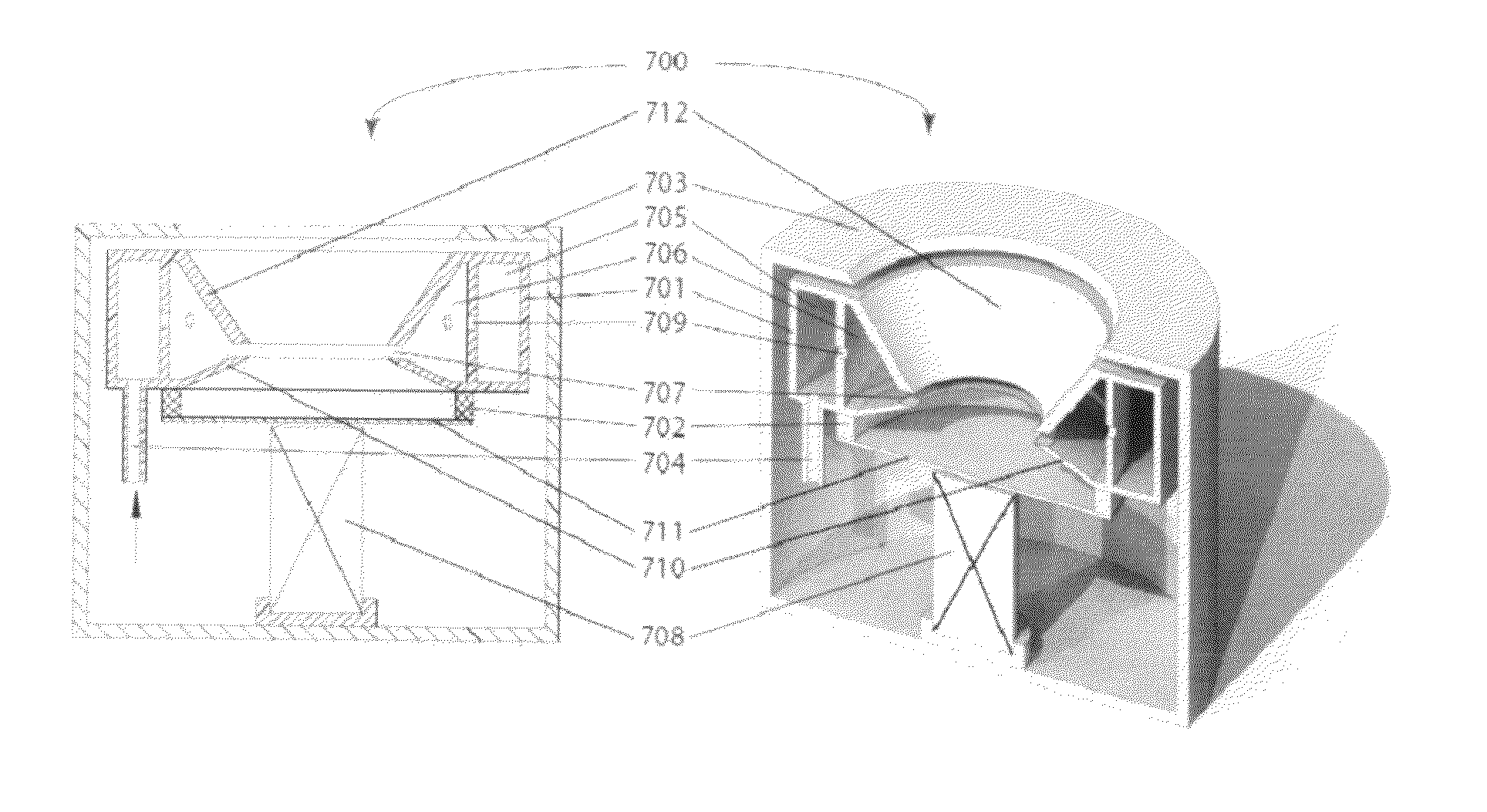
[0054]In this part of a patent there is described and shown in FIG. 6a a schematic and three-dimensional drawing of an end-Hall ion source with a multi-chamber anode with its simplest approach in a form of a two-chamber with introduction of a working gas from an anode first chamber into a second chamber and from a second chamber through a series of holes in a lower part of anode into a discharge channel that mainly consists of a hollow cone-type electrode occupying most part of a discharge channel. An end-Hall ion source of a multi-chamber design, as it will be seen from measurements of ion beam energy distributions and ion beam currents, shows a substantial improvements in comparison with above described in a Prior Art various end-Hall designs, demonstrating a quite narrow ion beam energy distribution with similar to a gridded ion source, except that, in this case, the ion beam energies are in the range of low energies from about 20 eV and up to about 200 eV with ion beam currents ...


PUM


Abstract

A Hall-current ion source with a narrow ion beam energy distribution is presented. A narrow ion beam energy distribution is provided by a utilization of a multi-chamber anode through which a working gas is applied and delivers a uniform working gas distribution in a discharge channel. Introduction of a working gas through a lower part of anode makes applied electric potential in a narrow area and leading to enhanced conditions for a working gas ionization, high ion beam current, high translation of a discharge voltage into a “monochromatic” ion beam mean energy distribution. A multi-chamber anode with a slit exit for introduction of a working gas into area under anode is utilized to prevent a backflow of insulating and dielectric depositions on anode parts, and under anode area makes a nominal operation with reactive gases without a phenomenon called as “anode poisoning” during long operating hours. The ion source with a shielded Hot Filament design shows very effective ion beam neutralization properties; it produces less heating of the substrate than a traditional one; it has a cleaner ion beam because its beam is not contaminated by the Hot Filament material particles. In the design with two Hot Filaments the ion source operation is extended for tens of hours.

Description

FIELD OF INVENTION[0001]This invention relates in general to the technology of ion and plasma sources, electric propulsion thrusters and other applications utilizing development of low energy ion beams, in particular to the industrial broad beam ion sources of a Hall-current ion type that are widely utilized in the thin film technology.BACKGROUND ART[0002]About 40 years ago main industrial ion sources were of so-called gridded types which are described in detail by H. Kaufman and R. Robinson in “Operation of Broad-Beam Sources”, Commonwealth Scientific Corporation, Alexandria, Va., 1987. These gridded ion sources are utilized for development of ion beams of low and medium energy (100-1500 eV) in varieties of thin film technologies for cleaning, etching, sputtering, deposition. However, despite of continued utilization of gridded ion sources at present time, they are not used broadly as it was earlier. That is because of their complexity, high cost and problems with an ion beam neutr...

Claims


Application Information

Patent Timeline
Patent Type & Authority Applications(United States)
IPC IPC(8): H01J27/02
CPCH01J27/146H01J37/08H01J2237/006H01J2237/31H01J2237/061H01J2237/08H01J2237/022
Inventor KLYUEV, EVGENY VITALIEVICHZHURIN, VIACHESLAV VASILIEVICH
Owner KLYUEV EVGENY VITALEVICH
Why Eureka
Try Eureka