Internal combustion engine

a combustion engine and combustion chamber technology, applied in the direction of combustion process measures, fuel systems, mechanical devices, etc., can solve the problems of unsatisfactory efficiency, high emissions, and engine as known from prior art also has an unsatisfactory efficiency, and achieves low pollutant emission, good torque response, and high efficiency.

Inactive Publication Date: 2012-02-09
WILLI FECHNER
View PDF5 Cites 19 Cited by
  • Summary
  • Abstract
  • Description
  • Claims
  • Application Information

AI Technical Summary

Benefits of technology

[0006]The object of the present invention is to provide an internal combustion engine, which is distinguished from other engines as kn

Problems solved by technology

The deficiencies of these engines, including unsatisfactory efficiency, high emissions, especially during cold starts, considerable noise and the like are known and are largely attributed to the fact that the transformation of liquid fuel into the gaseous state, the mixtu

Method used


Image

  • Internal combustion engine
  • Internal combustion engine
  • Internal combustion engine

Examples


second embodiment

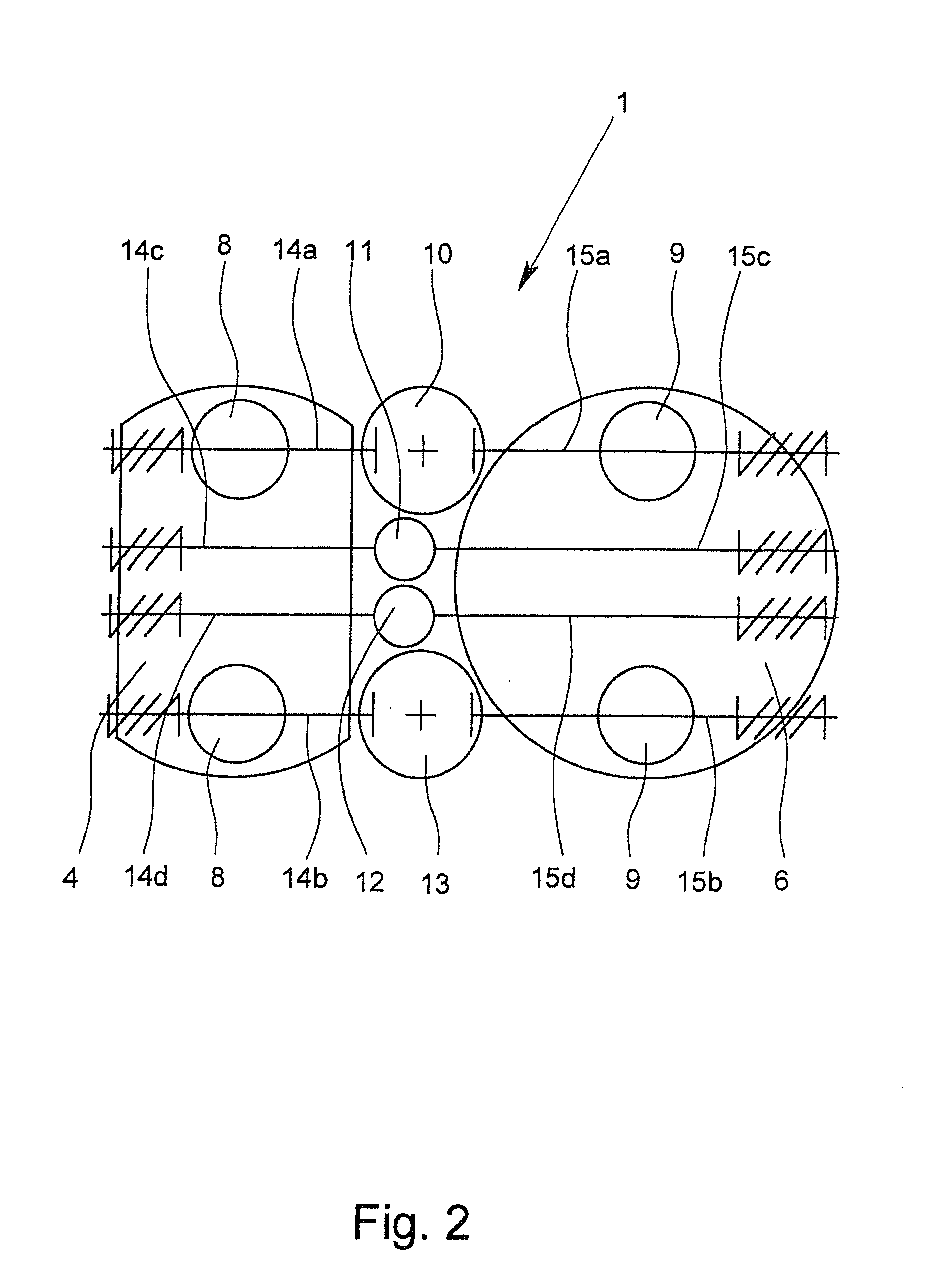
[0034]FIG. 2 shows an internal combustion engine 1 having four combustion chambers 10-13, wherein the combustion chamber inlet valves 14a-14d, and the combustion chamber outlet valves 15a-15d are arranged perpendicular to the longitudinal axis of the compression cylinder 4, and perpendicular to the longitudinal axis of the working cylinder 6. In doing so, the combustion of the fuel in the combustion chambers 10-13 is least disturbed by the valves 14a-14d, 15a-15d. However, basically, it is also possible that the combustion chamber inlet valves 14a-14d and / or the combustion chamber outlet valves 15a-15d are arranged parallel to the longitudinal axis of the compression cylinder 4 and / or to the longitudinal axis of the working cylinder 6 as represented in FIG. 1.

[0035]As is evident from FIG. 2, the combustion chambers 10 and 13 have a larger combustion chamber volume than the combustion chambers 11 and 12. At low speed in city traffic, when the cylinders have a lower degree of filling,...

fifth embodiment

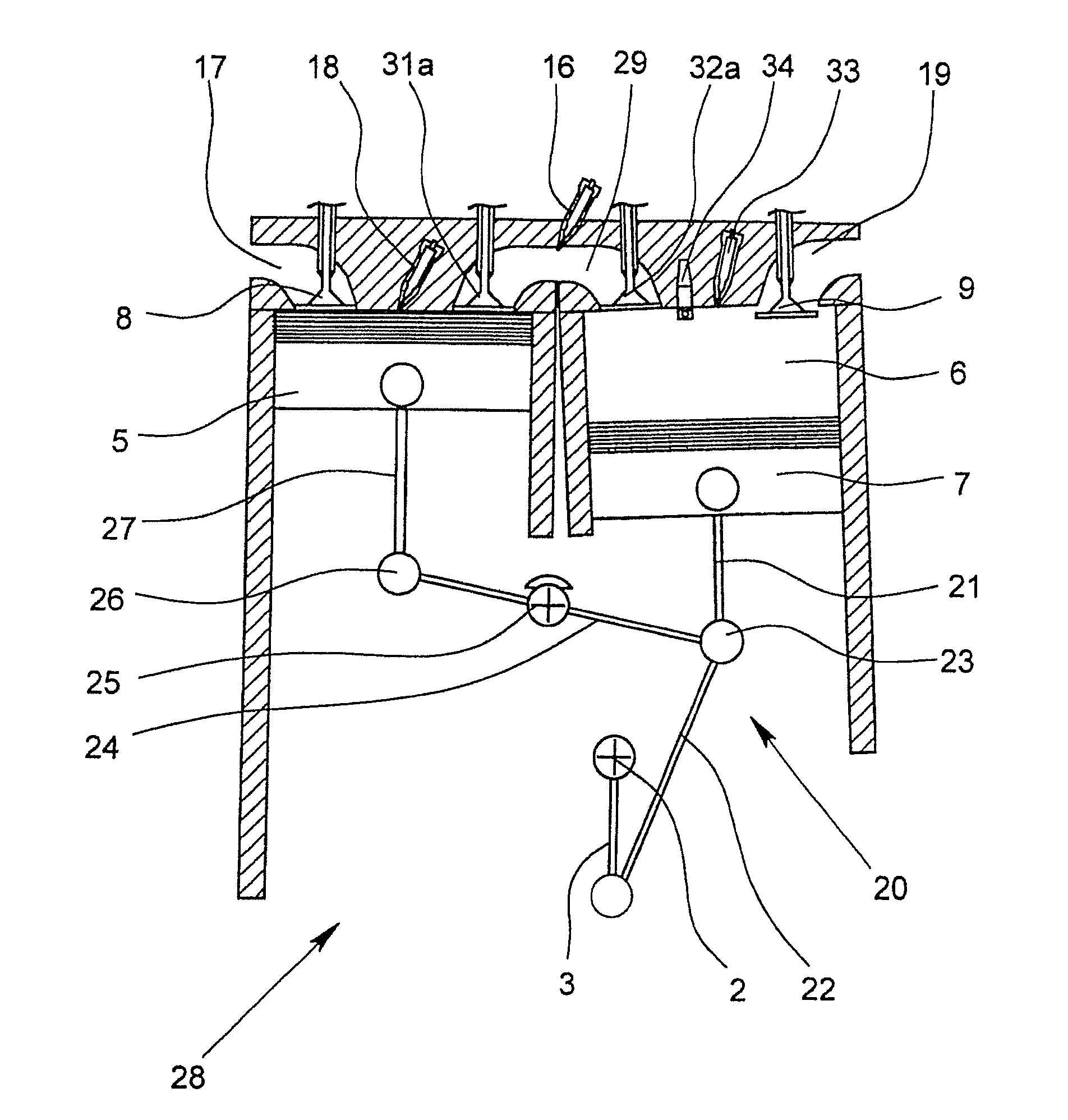
[0066]FIG. 7 shows an internal combustion engine 28, which essentially corresponds to the embodiment shown in FIG. 6, but in mirrored arrangement of compression piston 5 and working piston 7, which necessitates a different arrangement of the connecting rods for kinematic coupling of the working pistons 5, 7.

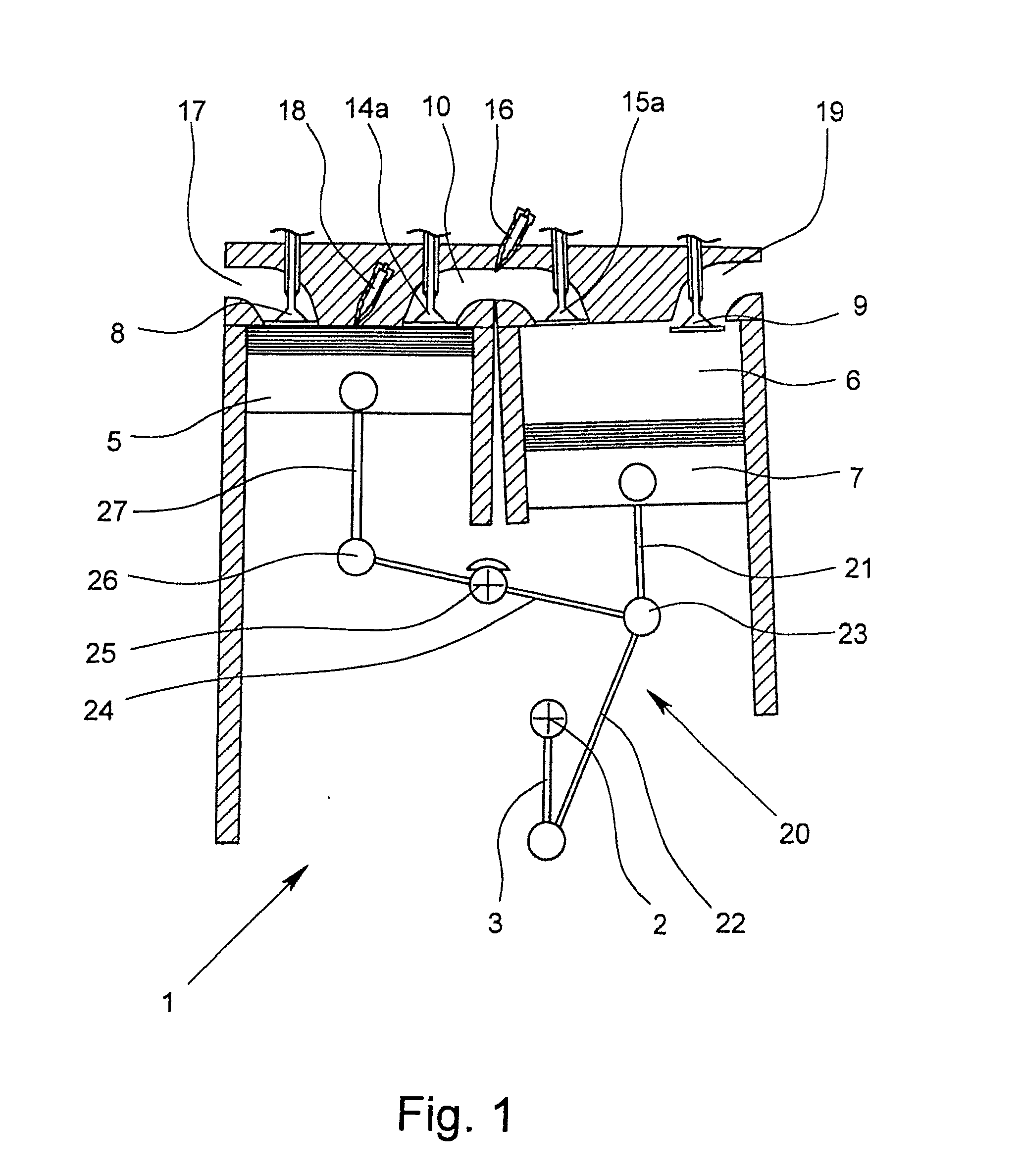
[0067]FIGS. 8 to 10 show further embodiments of internal combustion engines 28, wherein the working piston 7 is connected via a hinge to a multi-part link rod 20 with the crankshaft. The link rod 20 has in turn two connecting rods 21, 22, wherein the connecting rods 21, 22 are connected together at their ends by at least one first hinge (pivot pin) 23. The other end of a first connecting rod 21 is pivotably connected to the working piston 7 and the other end of a second connecting rod 22 is pivotably connected with two pivot pins 37, which receive the second connecting rod 22 and during operation, describe a circular path around the rotational axis of the crankshaft. The pivot pi...


PUM


Abstract

An internal combustion engine with a crankshaft, at least one compression piston which is housed in a compression cylinder, and at least one working piston which is housed in a working cylinder. Movement of the compression piston and of the working piston are coupled kinematically to movement of the crankshaft, so that the compression piston moves back and forth during a single revolution of the crankshaft in an intake stroke and a compression stroke and that the working piston moves back and forth during a single revolution of the crankshaft by a working stroke and an exhaust stroke. The compression cylinder has at least one inlet valve for drawing-in air into the compression cylinder during downward movement of the compression piston, and the working cylinder has at least one outlet valve for discharging combustion gases from the working cylinder during upward movement of the working piston.

Description

BACKGROUND OF THE INVENTION[0001]1. Field of the Invention[0002]The invention relates to an internal combustion engine with a crankshaft, at least one movable compression piston housed in a compression cylinder and at least one movable working piston housed in an operating cylinder, wherein the movement of the compression piston and the movement of the working piston are kinematically coupled to the movement of the crankshaft, so that, during a single revolution of the crankshaft by an intake stroke and a compression stroke of a four-stroke cycle, the compression piston moves back and forth and that the working piston moves back and forth during a single revolution of the crankshaft by a working stroke and an exhaust stroke of the same four-stroke cycle, wherein the compression cylinder has at least one inlet valve for drawing-in air into the compression cylinder with a downward movement of the compression piston and the working cylinder has at least one outlet valve for purging out...

Claims


Application Information

Patent Timeline
IPC IPC(8): F02B33/22F02B33/06
CPCF02B33/20F02B33/22F02B41/04Y02T10/32F02B75/32F02B2700/034F02G1/02F02B43/10Y02T10/30
Inventor STOCKHAUSEN, RALF
Owner WILLI FECHNER
Why Eureka
Try Eureka