Systems, compositions, and methods for fluid purification

a technology of fluid purification and composition, applied in the field of membrane structures, can solve the problems of limiting reproducibility, stability, separation performance of membranes, and difficult to get a defect-free interface between layers, and achieves high permeability, flux, selectivity.

Active Publication Date: 2012-02-09
THE OHIO STATE UNIV RES FOUND
View PDF9 Cites 91 Cited by
  • Summary
  • Abstract
  • Description
  • Claims
  • Application Information

AI Technical Summary

Benefits of technology

[0012]The present disclosure meets these and other needs by providing a membrane, which has, for example, high permeability, flux, selectivity, or a combination thereof.

Problems solved by technology

Typically thin membranes with small pores are stacked on thicker substrates with coarser pores, which provide mechanical support but do not significantly increase the resistance to flow.
In such membrane structures it is extremely difficult to get a defect-free interface between layers to ensure sufficient connectivity through the membrane structure.
A major limiting factor to the application of supported inorganic membranes, however, is the frequent occurrence of defects which limits reproducibility, stability, and the separation performance of the membranes.
Many thin microporous and dense gas separation membranes studied in the past have likely been affected by defects, leading to a large variation in the reported membrane performance, underestimation of selectivity, and overestimation of permeance.
Such meso- (2-50 nm) and macro-defects (>50 nm) have a deleterious effect on the gas separation performance due to significant contributions of Knudsen flow, viscous flow, or both to the overall flow.
These mechanisms result in a low selectivity or no selectivity at all.
In addition, CVD methods require significant investment in equipment, and are not easily incorporated in a viable, continuous fabrication process.
Thin, high permeance structures may be readily made via colloidal deposition methods known to those of skill in the art, however, colloidal methods are not self-repairing and often result in a substantial number of membrane defects.
Defects may arise as a result of imperfections in the deposition method, the deposition surface, or both.
Membrane support surfaces which contain sufficiently large defects, may result in the formation of large, pinhole defects after deposition due to inadequate bridging or coverage of the latent structural defects.
In addition to the high susceptibility of gas phase and colloidal synthesis methods to support defects, both methods often also suffer from environmental contamination during membrane fabrication processes.
Colloidal synthesis methods are also typically affected by defects from bubble generation during dispersion preparation, colloidal instability, and the removal of additives.
In addition, the removal of templating agents in ceramic membranes, especially zeolites, during calcination may also lead to the formation of intercrystalline defects such as grain boundary defects and cracks.
Counter-diffusion chemical liquid deposition (CLD) for defect patching and CVD post-synthesis modification have both been used with limited success to reduce defects in zeolites membranes.

Method used


Image

  • Systems, compositions, and methods for fluid purification
  • Systems, compositions, and methods for fluid purification
  • Systems, compositions, and methods for fluid purification

Examples


example 1

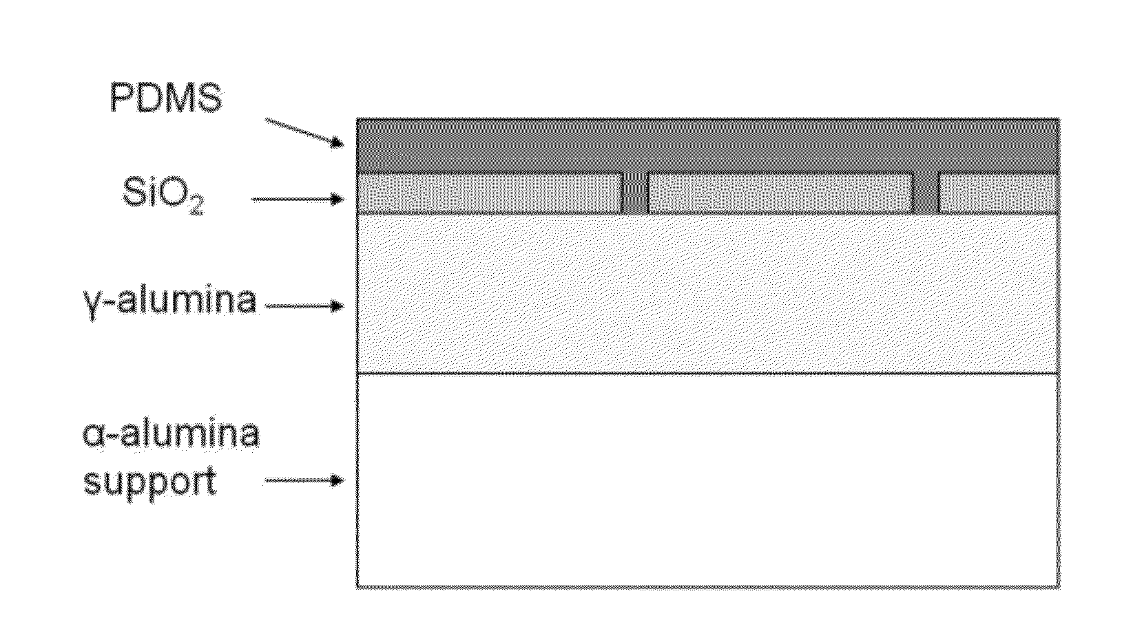
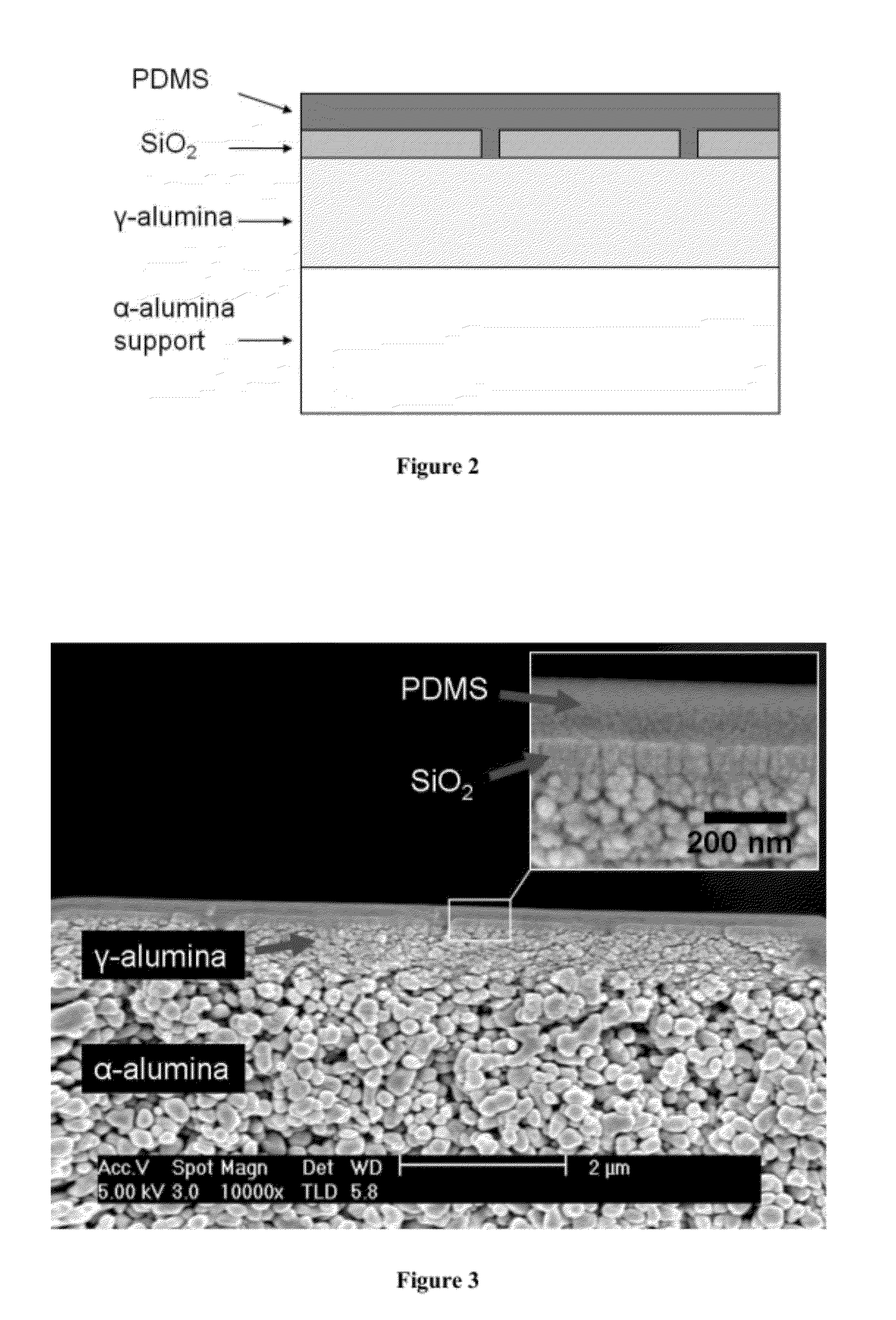
γ-Alumina-Polysulfone Composite Membrane (from an Aqueous Sol) Covered by a Poly(dimethylsiloxane) (PDMS) Defect Abatement Layer

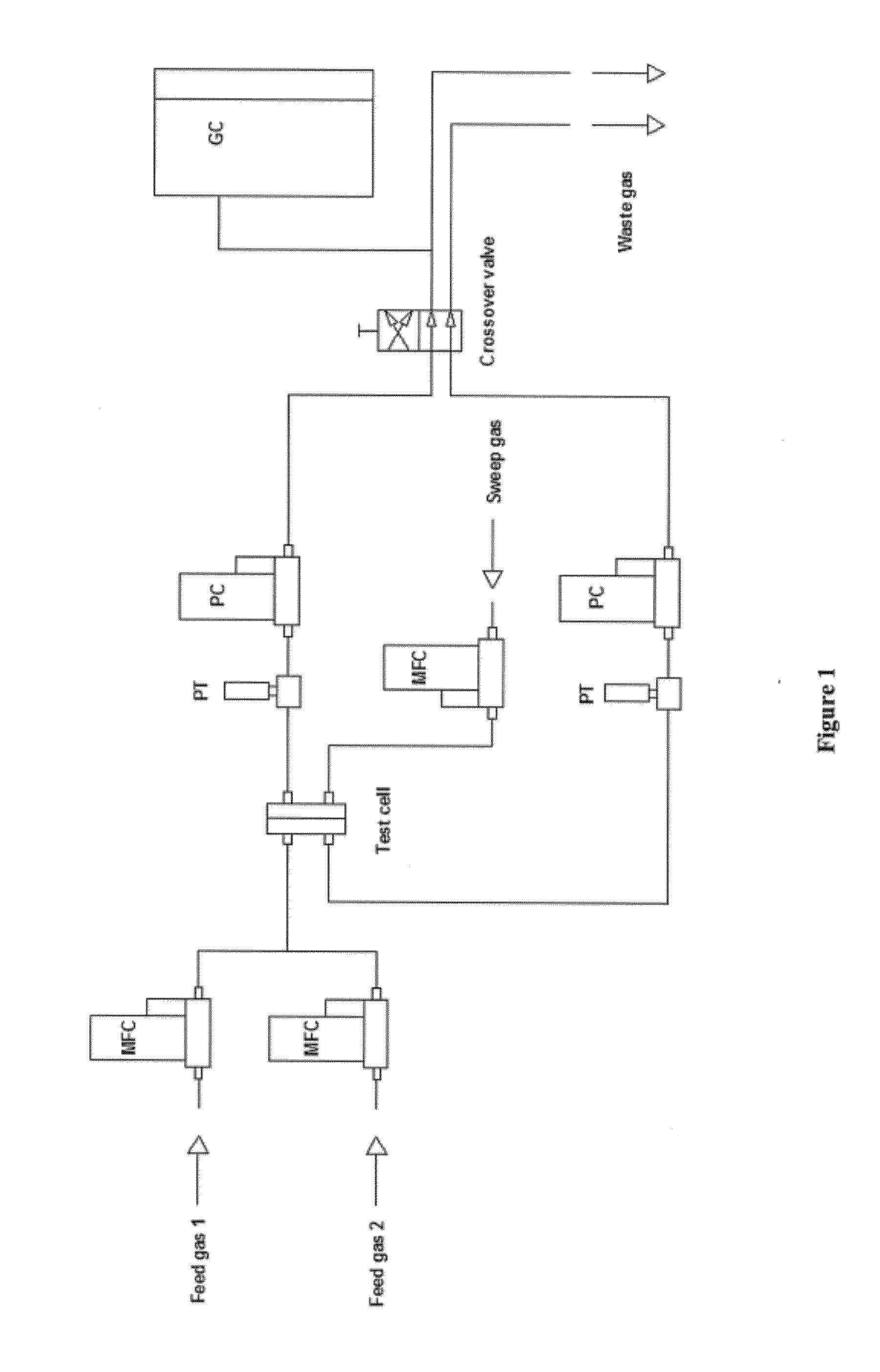
[0080]A Boehmite sol in water with ˜1 wt % concentration was prepared by hydrolysis of aluminum tri-sec-butoxide (ATSB) at 90° C. in a mixture with an ATSB:H2O molar ratio of 1:100, followed by peptization and purification (T. A. Kuzniatsova, M. L. Mottern, K. Shqau, D. Yu, H. Verweij, “Micro-structural optimization of supported γ-alumina membranes,”J. Membrane Sci., 316 [1] 80-88 (2008).). 1 mL sol was spin-coated on a polysulfone support (molecular weight cut-off of ˜50 kDa) placed on a thin circular metal plate, followed by overnight drying at room temperature, and rapid thermal processing (RTP) to transform Boehmite to the γ-alumina phase. This treatment was carried out 3× with spin coating conditions as follows: 1) 500→3000 rpm, 2) 500→1700→3000 rpm, and 3) 500→1700→3000 rpm. The sol was spread at 500 rpm during each coating, in the 2nd and 3rd treatme...

example 2

γ-Alumina-Polysulfone Composite Membrane (from an H2O / Iso-Propanol (IPA) Sol) and Covered by a Poly(Dimethylsiloxane) (PDMS) Defect Abatement Layer

[0082]A Boehmite sol in water with ˜1 wt % concentration was prepared by hydrolysis of aluminum tri-sec-butoxide (ATSB) at 90° C. in a mixture with an ATSB:H2O molar ratio of 1:100, followed by peptization and purification. It was dialyzed with water of pH ˜3.5 to remove any salts present. The sol was then diluted ˜0.4 wt % by adding IPA. The IPA addition resulted in better wetting of the polysulfone surface, and improved sol homogeneity. 1 mL sol was spin-coated on a polysulfone support (molecular weight cut-off of ˜50 kDa) placed on a thin circular metal plate, followed by overnight drying at 40° C. in H2O-saturated air, and rapid thermal processing (RTP) as in example 1 to transform the Boehmite to γ-alumina phase. After the sol was evenly spread on polysulfone, the spinning speed was increased from 250 to 1000 rpm in 10 sec, and kept ...

example 3

γ-Alumina-Polysulfone Composite Membrane from an H2O / Iso-Propanol Sol with Poly(Vinylpyrrolidone) (PVP) Addition, Covered by a Poly(Dimethylsiloxane) (PDMS) Defect Abatement Layer

[0084]A 0.4 wt % sol in water and IPA was made as in example 2. This sol was then mixed with a 3 wt % PVP-K15 solution in water of pH=2 in a volume ratio of 3 sol:2 PVP solution. Spin-coating with 1 ml sol, and RTP were performed as in example 2. The thus formed composite membrane was immersed in IPA at room temperature for 24 hours to remove the soluble PVP. The PVP addition had the effect of making the γ-alumina layer more porous and / or increase its pore size. The membrane was then dried for a couple of hours inside a clean hood to remove the volatile IPA. A PDMS defect abatement coating was applied as in example 1.

[0085]The permeation measurements were conducted as in example 1. A CO2 permeance of >151 GPU with a CO2 / N2 selectivity of >11 was obtained. A similar structure without alumina layer membrane g...


PUM

PropertyMeasurementUnit
pore sizeaaaaaaaaaa
thicknessaaaaaaaaaa
thicknessaaaaaaaaaa

Abstract

Disclosed herein are membranes comprising a substrate, a support layer, and a selective layer. In some embodiments the membrane may further comprise a permeable layer. Methods of forming membranes are also disclosed comprising forming a support layer on a substrate, removing adsorbed species from the support layer, preparing a solution containing inorganic materials of a selective layer, contacting the support layer with the solution, drying the membrane, and exposing the membrane to rapid thermal processing. Also disclosed are methods of fluid purification comprising providing a membrane having a feed side and a permeable side, passing a fluid mixture across the feed side of the membrane, providing a driving force for transmembrane permeation, removing from the permeate side a permeate stream enriched in a purified fluid, and withdrawing from the feed side a fluid that is depleted in a purified fluid.

Description

CROSS REFERENCE TO RELATED APPLICATION[0001]This application claims the benefit of U.S. Provisional Patent Application No. 61 / 364,623, filed Jul. 15, 2010, the entire content of which is incorporated herein by reference.STATEMENT REGARDING FEDERALLY SPONSORED RESEARCH[0002]This invention was made with government support under grant DGE0221678, awarded by the National Science Foundation, grants 22000109, DE-FG02-06ER15776, and 10020047, awarded by the U.S. Department of Energy, and grant LDRD 2007, awarded by PNNL / Battelle. The U.S. government has certain rights in the invention.BACKGROUND[0003]The present disclosure relates generally to membrane structures. More particularly, the disclosure relates to membrane structures having high flux and high selectivity. The disclosure also relates to methods of manufacturing membrane structures.[0004]Porous membrane structures are extensively used in filtration, separation, catalysis, detection, and sensor applications. Membrane structures wit...

Claims


Application Information

Patent Timeline
Patent Type & Authority Applications(United States)
IPC IPC(8): B01D71/70B01D71/48B01D71/56B01D71/40B01D71/68B05D3/00B01D71/02B01D71/04B01D69/10B01D67/00B05D3/02B01D71/00B01D71/32
CPCB01D67/0051B01D2323/30B01D67/0072B01D67/0079B01D67/009B01D69/02B01D69/10B01D69/105B01D69/12B01D69/148B01D71/022B01D71/024B01D71/025B01D71/028B01D71/44B01D71/68B01D71/70B01D67/0069
Inventor HO, W.S. WINSTONVERWEIJ, HENDRIKSHQAU, KRENARRAMASUBRAMANIAN, KARTIK
Owner THE OHIO STATE UNIV RES FOUND
Why Eureka
Try Eureka