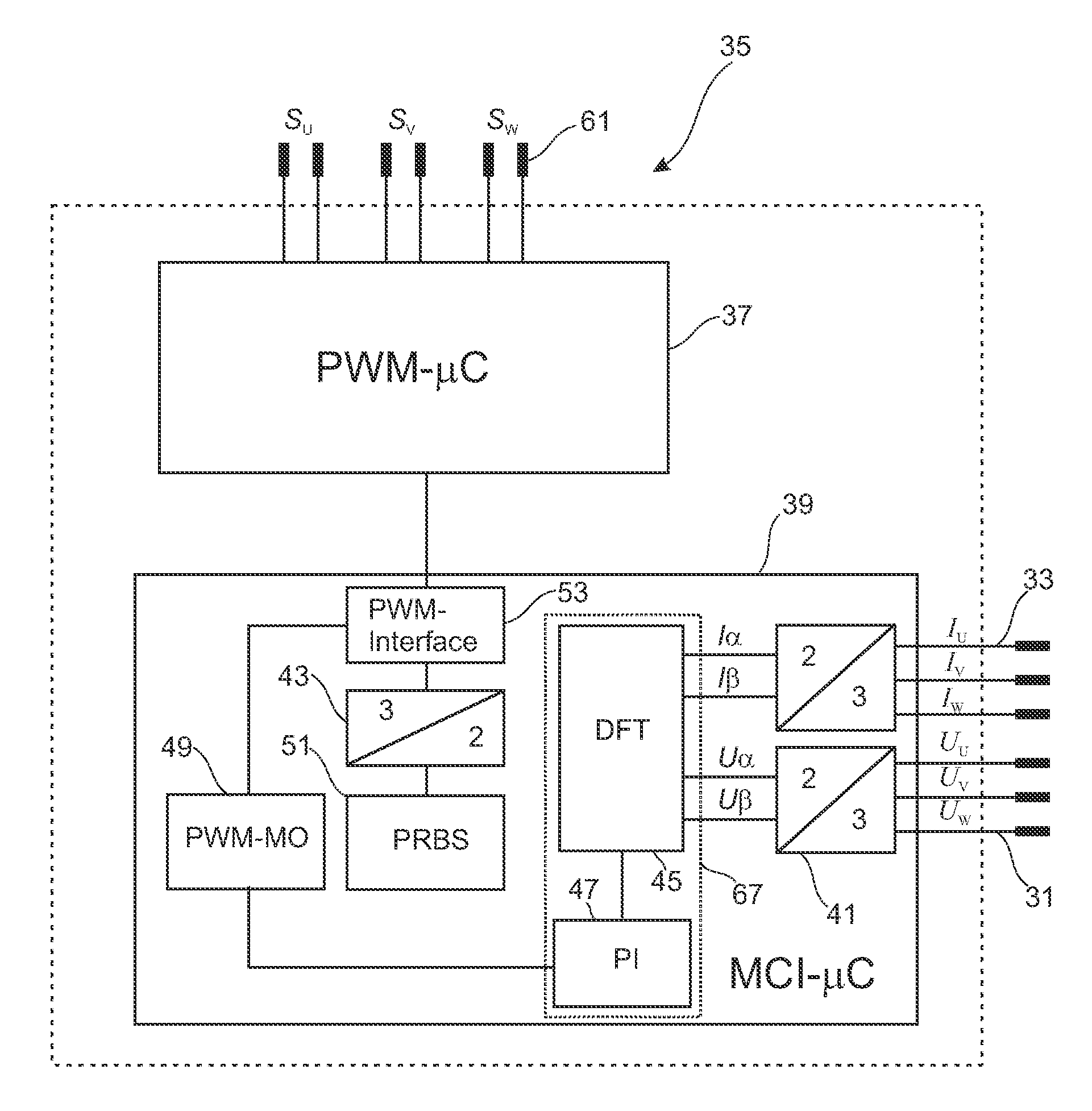
[0023]According to an advantageous further development, for example, the test signal can be a pseudo-
noise binary signal. The test signal should have a
high bandwidth in order to make possible the highest possible
frequency resolution and a
broadband analysis of the electrical
motor behavior.
White noise has a uniformly distributed
broadband frequency spectrum. A pseudo-
noise binary signal (PRBS) is a binary signal that approximates the spectrum of
white noise. It can typically assume the values +1 and −1 and is used alternatively to
white noise. In particular, the reproducibility of the signal is advantageous, whereby a PRB signal is frequently used in regulating technology for the analysis of an
impulse response by means of a maximum length sequence. A PRB test signal can be readily generated by linear feedback shift registers and can be produced, for example, by a DPS (
Digital Signal Processor), FPGA (
Field Programmable Gate Array) or microcontrollers of a motor
regulator for controlling the
inverter. Thus, every
motor control electronic
system can generate such a PRB signal without great modification and feed it in as motor
voltage into the motor.
[0024]Basically, a frequency range transformation of scanned
time range data can take place as desired for the identification of the equivalent circuit parameters in the frequency range. According to an advantageous further development of the invention the identification of the equivalent circuit parameters can comprise a Fourier transformation in accordance with a
periodogram method, preferably a Bartlett method, in particular a Welch method. A spectral
power density is achieved in the framework of a
periodogram method by a Fourier transformation of
individual data blocks. The quality of the spectral
estimation can be improved in that a number of periodograms that are independent of each other are averaged. This method is known in the literature under the name of Bartlett method, in which the measured signal is divided into sections. The Welch method represents an expansion of the procedure suggested by Bartlett. Certain window functions can be used here to reduce the leakage effect. The disturbing leakage effect occurs when the signal section is not periodic, a whole multiple of the period or when this signal section is on the edges of zero. The use of a Welch method in the identification of a
system of two or of three units is already known from the above-cited publication [2]. The Welch method splits M scanning values into K partial sequences that are weighted with a
window function and is applied to a Fourier transformation. The Welch method described in the publication [1] makes possible the transformation of any number of scanning values with the greatest possible accuracy into the frequency range. The
time range data is windowed here, the windowed data divided into partial sequences and Fourier-transformed and periodograms are determined from this that can be used to determine the
transmission function, in this instance the
admittance function, in the frequency range.
[0025]However, alternatively to the above, a
correlogram method, also known in the literature under the name Blackman-Tukey
estimation, can be used. Here, the spectral
estimation takes place on the basis of an autocorrelation function (AKF) and a cross
correlation function (KKF) that is calculated from the test signal (
excitation signal) and from the measured signal (response signal). In this formulation the spectral
power density is obtained by Fourier transformation of the previously estimated AKF and KKF. However, the Welch method furnishes more robust results.
[0033]Thus, it is conceivable to build the Fourier transformation means up as FPGA in order to realize a rapid Fourier transformation with the aid of a static switching circuit, and to implement the parameter identification means as variable calculating
software on a high-performance DSP of a motor control
regulator. A test
signal production and measured value storage can be carried out in an
inverter motor control device. Fourier transformation and parameter identification can also take place by a motor control device or by an external identification apparatus that comprises an interface to the communication with the motor control device. Thus, the motor control device can be provided with low calculating power, and demanding signal-theoretical tasks can be processed in an external identification apparatus that can be connected to the motor control device, as a result of which hardware expense can be saved.
[0034]According to an advantageous further development the apparatus can furthermore comprise a monitoring and optimization unit that is set up to determine, optimize and / or monitor
control parameters of an
inverter control apparatus on the basis of the identified equivalent circuit parameters. The monitoring and optimization unit receives the determined equivalent circuit parameters of the parameter identification unit and can optimize
control parameters of the motor control device on the basis of determined equivalent circuit parameters, in particular as regards a dynamic
regulator behavior and / or filter properties in order to reduce the effects of the inductive behavior of the asynchronous motor on the mains. Furthermore, an efficient operation of the motor control can be optimized and motor changes monitored and / or an
error signal can be emitted in the case of a motor failure or erroneous behavior. The equivalent circuit parameters required for this can be routinely carried out after a certain time interval or, for example, when replacing the motor or motor parts again in the framework of a conditioning monitoring by the monitoring and optimizing unit.


