
Intra-cavity second harmonic generation (SHG) laser device

a laser device and second harmonic generation technology, applied in the direction of laser details, optical resonator shape and construction, electrical apparatus, etc., can solve the problems of limiting the efficiency of frequency conversion and the spectral and temporal characteristics of laser output, chaotic radiation process switching between different modes, and noisy laser output, etc., to achieve increased spectral selectivity and prolong cavity length

Active Publication Date: 2012-03-01
UNIKLASERS
View PDF2 Cites 12 Cited by
  • Summary
  • Abstract
  • Description
  • Claims
  • Application Information

AI Technical Summary

Benefits of technology

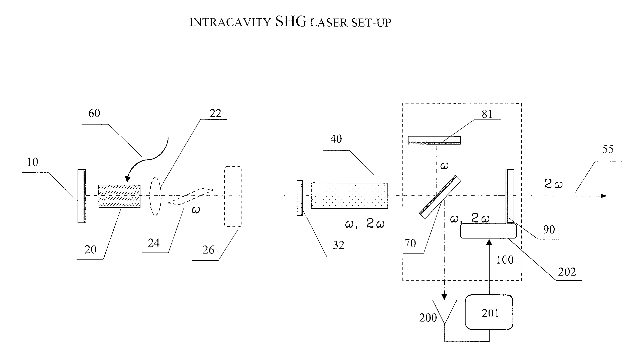
[0013]The optical path difference between two branches of the Michelson interferometer is chosen such as to narrow the spectral range of the nearly 100% reflectivity of the at least one of the laser cavity end reflector below its threshold value that tolerates to switch the laser from a single longitudinal mode operation to a multi longitudinal mode regime.
[0015]The optical path between the first Fabry-Perot reflecting element and the VBG is chosen such as to narrow the spectral range of the nearly 100% reflectivity of the at least one of the laser cavity end reflector below the spectral range threshold value that tolerates to switch from a single longitudinal mode operation to a multi longitudinal mode regime.
[0016]An advantage of making at least one of laser cavity end reflectors like Michelson or Fabry-Perot interferometric layouts incorporating a volume Bragg grating is that such layouts, starting from a selectivity of the VBG, further increase the spectral selectivity of the laser cavity end reflector without introducing an additional loss to the cavity. Hence, the laser is capable to operate in single longitudinal mode regime with reasonably long laser cavity (over 100 mm) providing a freedom for placing a nonlinear crystal of an optimal size and geometry for maximizing the SHG efficiency.
[0019]In some embodiments, the laser device tuning means consists of at least one piezoelectric actuator to control the position of at least one of the elements of the laser cavity end reflector, and an appropriate photo-electric feedback circuit that produces a controlling electrical signal being applied onto the piezo-electric actuator. This provides for a fine tuning the laser cavity longitudinal mode structure and for stabilization of the laser output power.

Problems solved by technology

This approach, however, has specific issues associated therewith that may limit the efficiency of the frequency conversion and the spectral and temporal characteristics of the laser output.
In particular, because of a competition among the laser cavity eigenmodes the radiation process is chaotically switching between different modes at the laser fundamental frequency.
Due to a nonlinear interaction this chaotic behavior of the laser is even stronger exposed at the second harmonic frequency resulting in a noisy laser output (so-called “green-noise”) that limits number of practical application.
In practice, however, placing a spectral selector inside the laser cavity leads to a decrease of the radiation power circulating through the nonlinear crystal, hence the efficiency of SHG also decreases.
With nearly 100% spectral peak reflectivity of a VBG this approach eliminates a decrease of circulating inside the cavity power at the laser fundamental frequency, however, it remains restrictive with concern to a single longitudinal mode selection when applied to the lasers of practical use for the intracavity SHG.
However, to accommodate a SHG nonlinear crystal of a practical significance additionally to a active laser crystal within such a short cavity is just not feasible.

Method used


Image

  • Intra-cavity second harmonic generation (SHG) laser device
  • Intra-cavity second harmonic generation (SHG) laser device
  • Intra-cavity second harmonic generation (SHG) laser device

Examples


Embodiment Construction

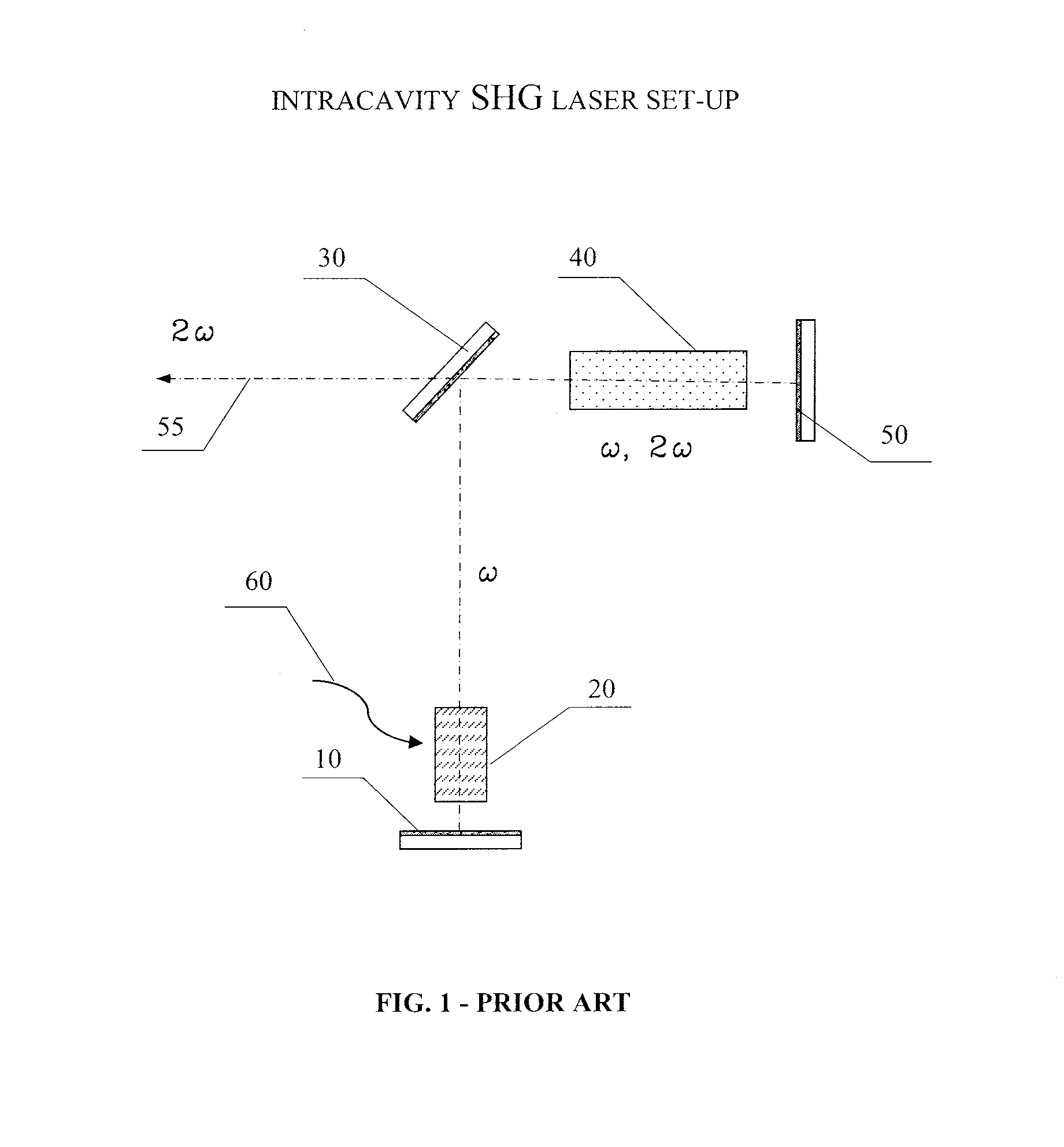
[0033]FIG. 1 shows a layout of laser cavity principal components previously suggested for intracavity frequency doubling, where the first cavity end reflector 10, active (laser gain) medium 20, nonlinear crystal 40, and the first cavity end reflector 50 comprise a linear type laser cavity, folded by the cavity folding mirror 30 for allowing unidirectional extraction of the power at frequency 2ω (second harmonic). The waved arrow 60 indicates that an appropriate excitation of the active medium 20 is provided. In such a layout all the cavity mirrors 10, 30, and 50 are made highly reflective about the laser fundamental frequency ω. Commonly to keep the cavity loss at minimum the reflectivity of these mirrors are made as close to 100% as technologically possible by mirror manufacturers. For uni-directional laser output the mirror 50 is also made highly reflective at the second harmonic frequency 2ω, while the folding mirror 30 is made as transmissive as possible at frequency 2ω. Due to ...


PUM


Abstract

A laser device for intra-cavity frequency conversion, in particular, for the second harmonic generation, the device comprising a laser cavity, formed by the first and the second laser cavity end reflectors wherein the said laser cavity end reflectors are highly reflective for the radiation about the laser fundamental frequency and as such provide for a predetermined level of circulating inside the cavity fundamental frequency power; an active medium provided within the said laser cavity; at least one non-linear crystal, in particular, for the second harmonic generation provided within the same laser cavity; tuning means adapted for tuning at least one of laser cavity end reflectors; wherein at least one of the laser cavity end reflectors comprises an interferometric layout providing spectrally selective reflection for the radiation about the laser fundamental frequency with the value of reflectivity nearly to 100% within a spectral range close to the free spectrum range of the laser cavity and with a sufficiently lower reflectivity outside the above spectral range such that the laser cavity restricts the spectrum of the laser radiation to a single longitudinal mode.

Description

CROSS-REFERENCE TO RELATED APPLICATIONS[0001]This application claims the benefit of European Patent Application No. 10173991.0, filed Aug. 25, 2010, the entire disclosures of which is herein incorporated by reference.FIELD OF THE INVENTION[0002]The present invention relates to frequency conversion of laser radiation by means of non-linear interaction of the electromagnetic radiation with a suitable nonlinear optical medium. In particular, the invention relates to an intracavity Second Harmonic Generation (SHG), also called frequency doubling, laser device.[0003]In a SHG process, the efficiency of the conversion of laser power at a fundamental frequency into power at the second harmonic frequency is strongly dependent on the intensity of radiation applied to the nonlinear optical material employed for the frequency conversion. Known nonlinear optical materials may require interacting intensities within a range of 106 to 10° W / cm2 for achieving practically significant conversion effic...

Claims


Application Information

Patent Timeline
Patent Type & Authority Applications(United States)
IPC IPC(8): H01S3/10
CPCH01S3/08009H01S3/08036H01S3/0812H01S3/139H01S3/105H01S3/1062H01S3/109H01S3/0826
Inventor KARPUSHKO, FEDOR
Owner UNIKLASERS
Learn More