
Localized metal contacts by localized laser assisted conversion of functional films in solar cells

a solar cell and functional film technology, applied in the field of solar cells, can solve the problems of cell complexity and corresponding manufacturing costs, and achieve the effects of reducing the shadowing of the solar cell, reducing the recombination of carriers, and high conductivity of the metal grid

Inactive Publication Date: 2012-03-15
TETRASUN
View PDF11 Cites 46 Cited by
  • Summary
  • Abstract
  • Description
  • Claims
  • Application Information

AI Technical Summary

Benefits of technology

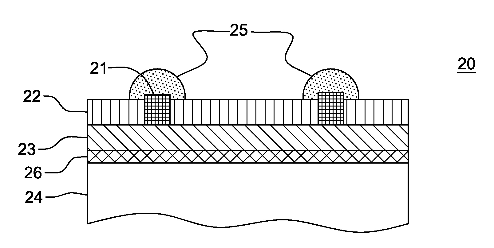
[0005]The present invention provides a solar cell structure and a method of manufacture which provide the benefits of low shadowing of the solar cell, commonly caused by excessive surface coverage from the metal electrodes, a high conductivity of the metal grid, and minimized carrier recombination underneath the metal contacts on, e.g., the front illuminated side of the cell, or any other side of the cell. The techniques disclosed enable use of multifunctional layers which also include integral electrical contacts, and manufacturing techniques which decrease the number of materials and processing steps needed, thereby reducing solar cell manufacturing costs.
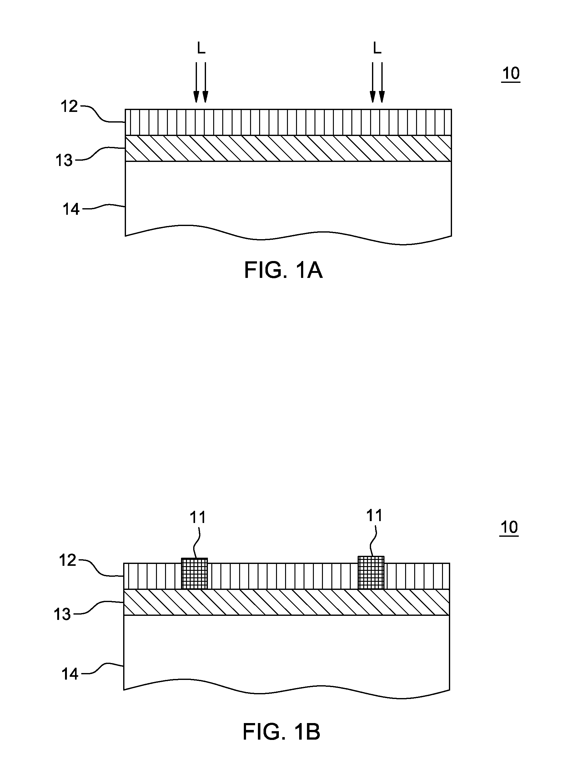
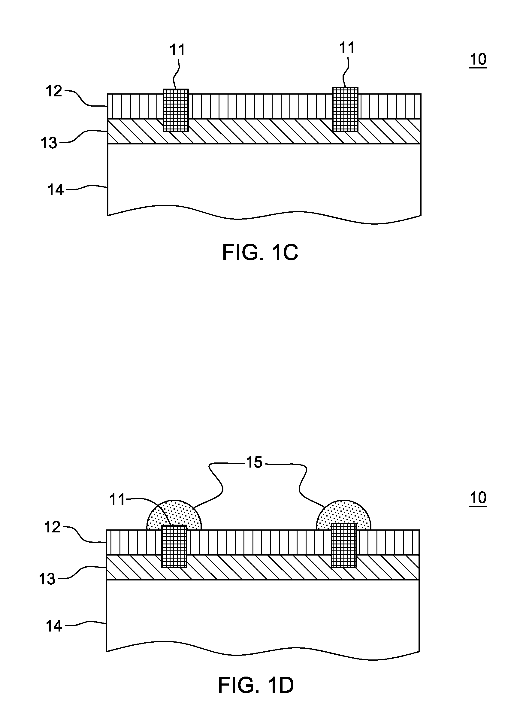
[0006]The present invention addresses the requirement for reduced complexity and corresponding manufacturing costs and processing steps by selectively converting the electrical conductivity state of a single, e.g., deposited dielectric insulating film, using direct laser energy impingement on the film, to form solar cell electrical contacts and interconnects without multiple deposition and patterning steps.

Problems solved by technology

Typically the number of layers, and each layer's associated processing steps (pre-clean, semiconductor film deposition, patterning-etch, pre-clean, metal deposition, and metal pattern-etch; etc.) contribute to cell complexity and corresponding manufacturing costs.

Method used


Image

  • Localized metal contacts by localized laser assisted conversion of functional films in solar cells
  • Localized metal contacts by localized laser assisted conversion of functional films in solar cells
  • Localized metal contacts by localized laser assisted conversion of functional films in solar cells

Examples


Embodiment Construction

[0028]The present invention is directed to effecting a local change of a solar cell's layer composition by laser irradiation, during which a metal contact to the underlying layer(s) or across the front surface is established through or embedded into, e.g., an insulating dielectric. In one embodiment, the metal contacts can be interconnected to form a continuous contact grid of, e.g., fingers and / or bus-bars.

[0029]This local change in chemical composition is achieved for films which comprise metal containing compounds, for example, aluminum nitride, titanium oxide, aluminum oxide, boron nitride, silicon carbide or silver containing transparent layers. Some of these materials can be transparent binary ceramics. Another exemplary class of materials includes transparent conductive oxides (TCOs) such as aluminum doped zinc oxide or fluorine doped tin oxide or indium tin oxide or zinc tin oxide, etc.

[0030]Many of these metallic compounds have ideal optical properties for solar cells, name...


PUM


Abstract

A solar cell, including contact metallization formed using selective laser irradiation. An upper layer is formed in the solar cell including a material which can be selectively modified to electrical contacts upon laser irradiation. Selective laser irradiation is applied to at least one region of the upper layer to form at least one electrical contact in the layer. A remaining region of the upper layer may be a functional layer of the solar cell which need not be removed. The upper layer may be, e.g., a transparent, conductive film, and anti-reflective film, and / or passivation. The electrical contact may provide an electrically conductive path to at least one region below the upper layer of the solar cell.

Description

RELATED APPLICATION INFORMATION[0001]This application claims the benefit of previously filed U.S. Provisional Application entitled “Localized Metal Contacts By Localized Laser Assisted Reduction Of Metal-Ions In Functional Films, And Solar Cell Applications Thereof,” filed 22 Apr. 2009 and assigned application No. 61 / 171,491; and is related to the commonly-assigned, previously filed U.S. Provisional Application entitled “High-Efficiency Solar Cell Structures and Methods of Manufacture,” filed 21 Apr. 2009 and assigned application No. 61 / 171,194; and to commonly-assigned, co-filed International Patent Application entitled “High-Efficiency Solar Cell Structures and Methods of Manufacture” filed as Attorney Docket No. 3304.001AWO and assigned application number ______. Each of these applications is hereby incorporated by reference herein in its entirety. All aspects of the present invention may be used in combination with any of the disclosures of the above-noted applications.TECHNICAL...

Claims


Application Information

Patent Timeline
Patent Type & Authority Applications(United States)
IPC IPC(8): H01L31/0224H01L31/02H01L31/04H01L31/18
CPCY02E10/50H01L31/022425Y02E10/547
Inventor CRAFTS, DOUGLAS E.
Owner TETRASUN
Learn More