
High efficiency drive method for driving LED devices

a driving led and high-efficiency technology, applied in the direction of electric variable regulation, process and machine control, instruments, etc., can solve the problems of low power handling capability, steep current-voltage curve in the conduction region, and low relative cost of the device and the drive circuitry, so as to improve the current balancing accuracy

Inactive Publication Date: 2012-03-15
SUNTEC ENTERPRISES
View PDF10 Cites 35 Cited by
  • Summary
  • Abstract
  • Description
  • Claims
  • Application Information

AI Technical Summary

Benefits of technology

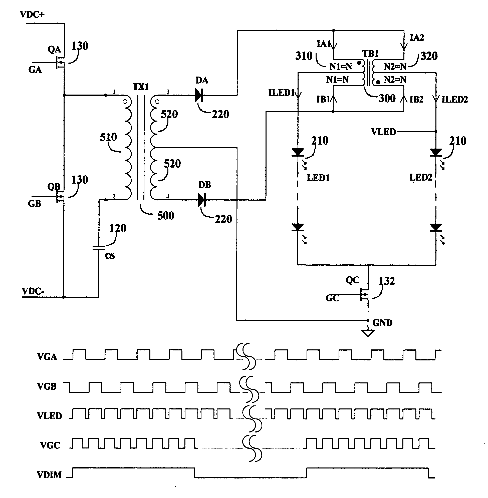
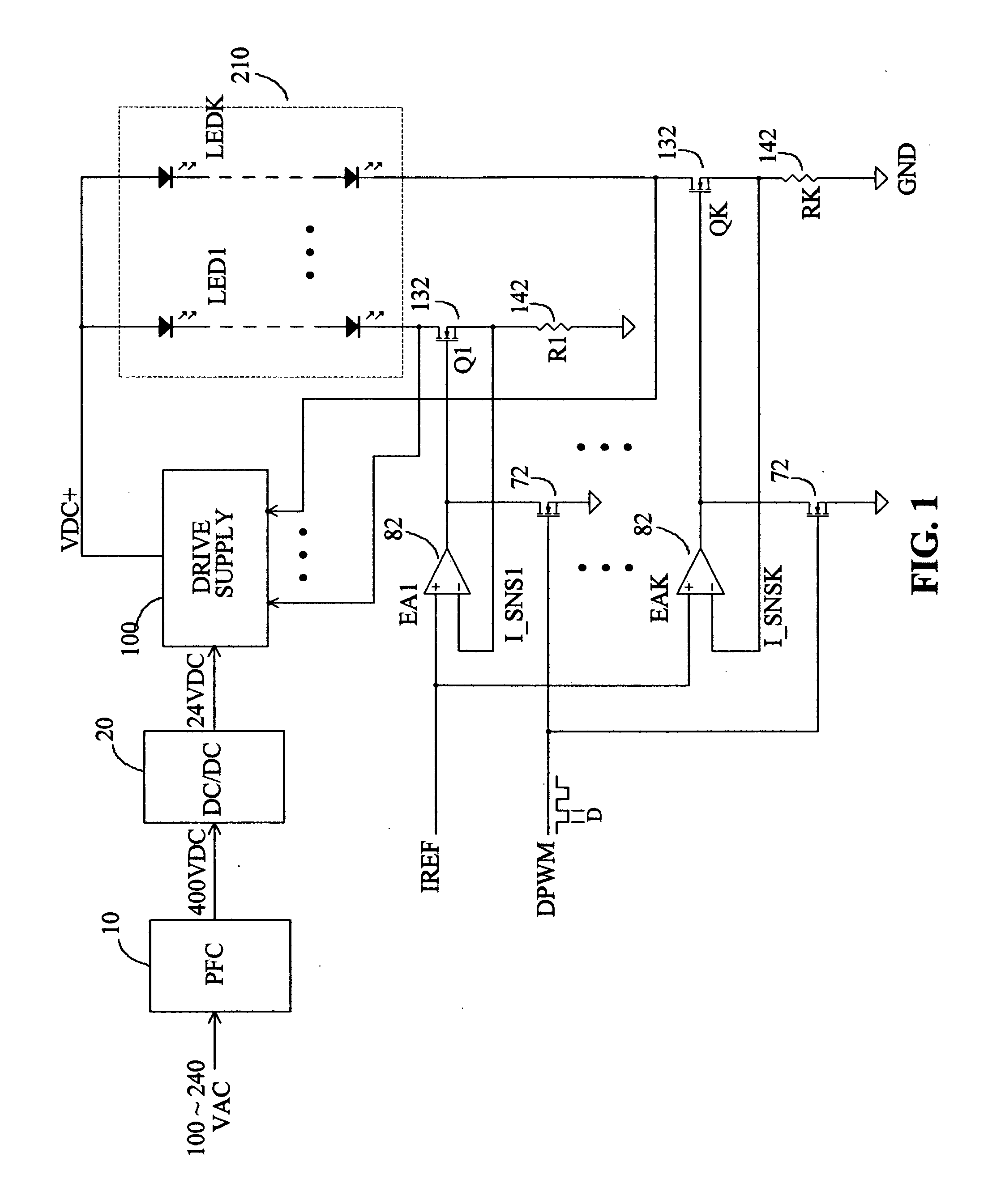
[0010]This invention discloses a set of concept to drive multiple LED devices with unique current balancing technique, high efficiency circuit operation and simplified power conversion process. The proposed concept eliminates the conventional dissipative current balancing approach and instead, uses a set of non-dissipative balancing concept to drive multiple LED strings with matched brightness and current control. Considerations are also taken to drive the LED devices with minimized power conversion process, reliable device fault handling, and elimination of high voltage sensing circuitry etc. to provide practical high efficiency, low cost drive solutions for LED lighting and backlight applications. Finally, a unique concept is disclosed to control the current and digital dimming duty of the LED strings independently with a non-dissipative drive method.
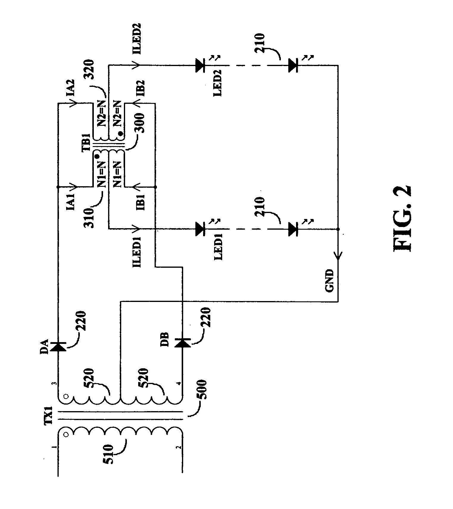
[0011]In one embodiment a balancing network with center-tapped balancing transformer is introduced to provide a loss-less current balancing for the LED strings. Particular considerations are made to maintain AC excitation for the transformer core while supplying DC current to the LED strings through the transformer windings. Apart from the loss-less balancing function, the balancing network also provides easy fault detection and robust fault tolerant operations.
[0014]In another embodiment the LED strings are controlled independently with separate regulation devices. The leakage inductance of the transformer winding is utilized to balance the LED current. The regulation switch further improves the current balancing accuracy by PWM switching regulation and in the meanwhile, controls the digital dimming operation by turning on and off its switching action in accordance with the digital dimming signal.

Problems solved by technology

Despite the various advantages of the LED device, the relatively high cost of the device and the drive circuitry and low power handling capability also draw major concerns in its applications and design considerations.
Because of the high cost of high power LED, e.g. devices around 1 W or so, and thermal management challenges related to the concentrated heat dissipation, most applications today use a high number of low power LED's normally from a few tens to a few hundreds to provide the particular light intensity required for the application.
With such high number of devices, circuit configuration is inevitably one of the top level design considerations that largely defines the architecture and total cost of the lighting system.
When the LED is forward biased, its forward current increases considerably with a small increase of the forward voltage, resulting in a steep current-voltage curve in the conduction region.
This nature obviously gives rise to a challenge of LED current control when connecting multiple devices in parallel.
But in large systems such as LCD backlight applications multiple LED strings still have to be used because of the limit of string voltage from safety and other design concerns and system reliability considerations.
In such cases the brightness matching or current balancing of the LED strings becomes a major challenge in the system design.
Mismatched LED current will result in uneven brightness distribution and deterioration of the system life.
Such requirement brings another challenge to the LED drive control.
Such dissipation not only reduces the efficiency of the system, but also generates excessive heat that creates thermal problems, resulting in higher design complexity, higher system cost and lower reliability.
If a short fault occurred with an LED element in a string, the corresponding regulating device has to drop additional voltage of the shorted LED and dissipate more power, which in turn will often result in over temperature of the device.
Such approach involves multiple power conversion stages that on one hand lowers the system efficiency and on the other hand holds the system cost high, both resulting in critical disadvantages to the further success of the LED lighting solutions.

Method used


Image

  • High efficiency drive method for driving LED devices
  • High efficiency drive method for driving LED devices
  • High efficiency drive method for driving LED devices

Examples


Embodiment Construction

[0026]As described above that the purpose of this invention is to provide an optimum approach to drive multiple LED strings with high efficiency operation and low system cost. Therefore the concept disclosed herein does not use any type of dissipative drive method for the LED control. The first concept is to use center-tapped magnetic components to drive multiple LED strings. FIG. 2 shows an example of such approach. As shown in FIG. 2, a power transformer 500 supplies drive power from its center-tapped secondary winding 520 to the LED strings 210, through the rectifier diode 220 and balancing transformer 300. Balancing transformer 300 has two windings 310 and 320 with equal number of turns and both have a center tap. The two rectifier diodes D1 and D2, represented as 220 are connected between the two supply terminals of the power transformer secondary winding and the receiving terminals of the balancing transformer. The two LED strings LED1 and LED2, represented as 210, are connect...


PUM


Abstract

A set of unique concept of driving multiple LED strings with non-dissipative current balancing and non-dissipative synchronous current regulation is disclosed. Inductive components and capacitive components are utilized in the non-dissipative current balancing approach to drive the LED strings from AC supply source. The synchronous regulation method regulates the LED current with pulse width modulated switching action in synchronous with the AC supply source frequency. Both simultaneous and independent control of the LED string operation can be realized with synchronous regulation method when combined with suitable circuit configuration.

Description

BACKGROUND OF THE INVENTION[0001]1. Field of the Invention[0002]This invention generally relates to methods and apparatus of driving LED devices, and more particularly, to some unique techniques to drive multiple LED devices with low cost circuits while minimizing the power dissipation in LED current regulation and dimming control.[0003]2. Description of the Related Art[0004]Light Emitting Diode (referred as LED hereinafter) is bringing revolutionary changes to the lighting industry and the world economy. High efficiency, compact size, long life and minimal pollution etc. are some of the main advantages that provide people elegant lighting solutions and in the meanwhile perfectly fit into the green power initiative. Because LED is made with solid substances, in lighting industry it is also called Solid State Lighting (referred as SSL hereinafter) device. The inherent mechanical robustness of SSL device together with the features described above also enable itself to provide more rel...

Claims


Application Information

Patent Timeline
IPC IPC(8): H05B41/36
CPCH05B33/0815Y02B20/347H05B33/0851H05B33/0827H05B45/10H05B45/46H05B45/35Y02B20/30H05B45/382H05B45/39
Inventor FAN, JIANPING
Owner SUNTEC ENTERPRISES
Learn More