Method for manufacturing positive electrode active material for energy storage device and energy storage device

a technology of energy storage device and active material, which is applied in the direction of sustainable manufacturing/processing, non-metal conductors, cell components, etc., can solve the problems of approximation and much heavier weight of electric vehicle batteries, and achieve the reduction of volume and weight of positive electrodes, the reduction of carbon coatings in the volume of positive electrodes, and the reduction of the volume of conduction auxiliary agents

Active Publication Date: 2012-04-12
SEMICON ENERGY LAB CO LTD
View PDF5 Cites 94 Cited by
  • Summary
  • Abstract
  • Description
  • Claims
  • Application Information

AI Technical Summary

Benefits of technology

[0007]An electric vehicle has lower environmental load and lower fuel cost in driving than a conventional vehicle using fossil fuel such as gasoline. However, the weight of a battery used in the electric vehicle is approximately 300 kg to 600 kg and is much heavier than the weight of fuel for the conventional vehicle, which is approximately 20 kg to 60 kg. Moreover, in spite of such a large difference in weight, the running distance of the electric vehicle is approximately one fifth to one third of that of the conventional vehicle in one refueling equivalent.
[0008]In view of the above problems, it is an emergent object to reduce the weight of a battery used in an electric vehicle or to increase the capacity of the battery.

Problems solved by technology

However, the weight of a battery used in the electric vehicle is approximately 300 kg to 600 kg and is much heavier than the weight of fuel for the conventional vehicle, which is approximately 20 kg to 60 kg.

Method used


Image

  • Method for manufacturing positive electrode active material for energy storage device and energy storage device
  • Method for manufacturing positive electrode active material for energy storage device and energy storage device
  • Method for manufacturing positive electrode active material for energy storage device and energy storage device

Examples


embodiment 1

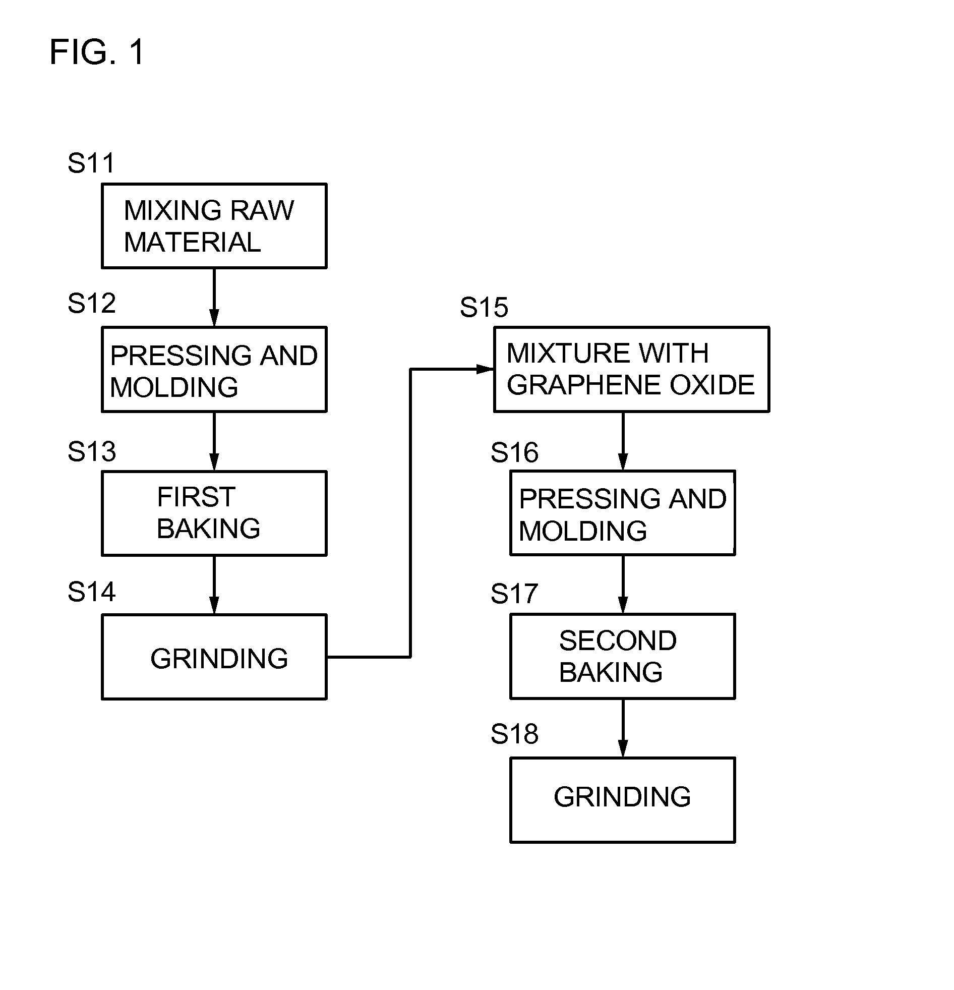
[0035]In this embodiment, a method for manufacturing a positive electrode active material for a lithium-ion secondary battery which is one embodiment of the present invention will be described with reference to FIG. 1.

[0036]As a main material included in the positive electrode active material, LiFePO4, LiNiPO4, LiCoPO4, LiMnPO4, Li2FeSiO4, or Li2MnSiO4 can be used.

[0037]For example, in the case of using LiFePO4 as the main material included in the positive electrode active material, Li2CO3, FeC2O4.2H2O, and NH4H2PO4 which are raw materials are mixed with an organic solvent (such as acetone), are finely ground with a ball mill, and are mixed uniformly (Step S11). After that, the mixture of the raw materials is pressed and molded into pellets (Step S12), and first baking is performed (Step S13). The first baking may be performed at a temperature of 250° C. to 450° C. for 1 hour to 48 hours in an inert atmosphere (such as a nitrogen atmosphere or a rare gas atmosphere), in a reducing a...

embodiment 2

[0054]In this embodiment, an energy storage device using the positive electrode active material obtained by the manufacturing method described in Embodiment 1 will be described taking a lithium-ion secondary battery as an example. The schematic structure of the lithium-ion secondary battery will be described with reference to FIG. 3.

[0055]Description is made below with reference to FIG. 3. FIG. 3 schematically illustrates the structure of a coin-type secondary battery. A slurry formed by mixing a binder into the positive electrode active material described in Embodiment 1 is applied onto a positive electrode current collector 228, molded, and then dried, whereby a positive electrode active material 230 is formed. As a material for the positive electrode current collector 228, aluminum is preferably used.

[0056]As the binder, a polysaccharide, a thermoplastic resin, a polymer with rubber elasticity, and the like can be given. Examples thereof include starch, polyvinyl alcohol, carboxy...

embodiment 3

[0064]In this embodiment, an example of a lithium-ion secondary battery which is an energy storage device different from that in Embodiment 2 will be described. The schematic structure of the lithium-ion secondary battery is illustrated in FIG. 4.

[0065]In the lithium-ion secondary battery illustrated in FIG. 4, a positive electrode 302, a negative electrode 307, and a separator 310 are provided in a housing 320 which isolates the components from the outside, and the housing 320 is filled with an electrolyte solution 311. In addition, the separator 310 is provided between the positive electrode 302 and the negative electrode 307.

[0066]A positive electrode active material 301 is formed in contact with a positive electrode current collector 300. Here, the positive electrode active material 301 and the positive electrode current collector 300 provided with the positive electrode active material 301 are collectively referred to as the positive electrode 302.

[0067]On the other hand, a neg...


PUM

PropertyMeasurementUnit
thicknessaaaaaaaaaa
particle diameteraaaaaaaaaa
total thicknessaaaaaaaaaa

Abstract

An energy storage device having high capacity per weight or volume and a positive electrode active material for the energy storage device are manufactured. A surface of a main material included in the positive electrode active material for the energy storage device is coated with two-dimensional carbon. The main material included in the positive electrode active material is coated with a highly conductive material which has a structure expanding two-dimensionally and whose thickness is ignorable, whereby the amount of carbon coating can be reduced and an energy storage device having capacity close to theoretical capacity can be obtained even when a conduction auxiliary agent is not used or the amount of the conduction auxiliary agent is extremely small. Accordingly, the amount of carbon coating in a positive electrode and the volume of the conduction auxiliary agent can be reduced; consequently, the volume of the positive electrode can be reduced.

Description

TECHNICAL FIELD[0001]The present invention relates to a method for manufacturing a positive electrode active material for an energy storage device and to an energy storage device.BACKGROUND ART[0002]With an increase in concern for the environmental issues, energy storage devices such as secondary batteries and electric double layer capacitors used for power supply for hybrid vehicles have been actively developed. As the energy storage devices, a lithium-ion battery and a lithium-ion capacitor having high energy performance have attracted attention. The lithium-ion battery, which is compact but can store a large amount of electricity, has been already mounted on a portable information terminal such as a mobile phone or a laptop personal computer, and has helped miniaturization of products.[0003]The secondary battery and the electric double layer capacitor have a structure in which an electrolyte is provided between a positive electrode and a negative electrode. It is known that each ...

Claims


Application Information

Patent Timeline
Patent Type & Authority Applications(United States)
IPC IPC(8): H01M4/36H01M4/583H01M4/58H01M4/136
CPCH01M4/136Y02E60/122H01M4/0433H01M4/625H01M4/1397H01M4/366H01M4/5825H01M4/0471Y02E60/10H01M2004/028C01B25/45C01B32/198H01M10/052C01P2004/80Y02P70/50H01M4/38
Inventor NOMOTO, KUNIHARUMIWA, TAKUYAYAMAKAJI, MASAKIKAWAKAMI, TAKAHIRO
Owner SEMICON ENERGY LAB CO LTD
Why Eureka
Try Eureka