

Gas turbine shroud with ceramic abradable layer
a technology of ceramic abradable layer and gas turbine, which is applied in the direction of machines/engines, liquid fuel engines, forging/pressing/hammering apparatus, etc., can solve the problems of falling off, unsatisfactory assurance, and damage to a part of the thermally sprayed coating film, and achieve high operation efficiency
- Summary
- Abstract
- Description
- Claims
- Application Information
AI Technical Summary
Benefits of technology
Problems solved by technology
Method used
Image

Examples
example 1
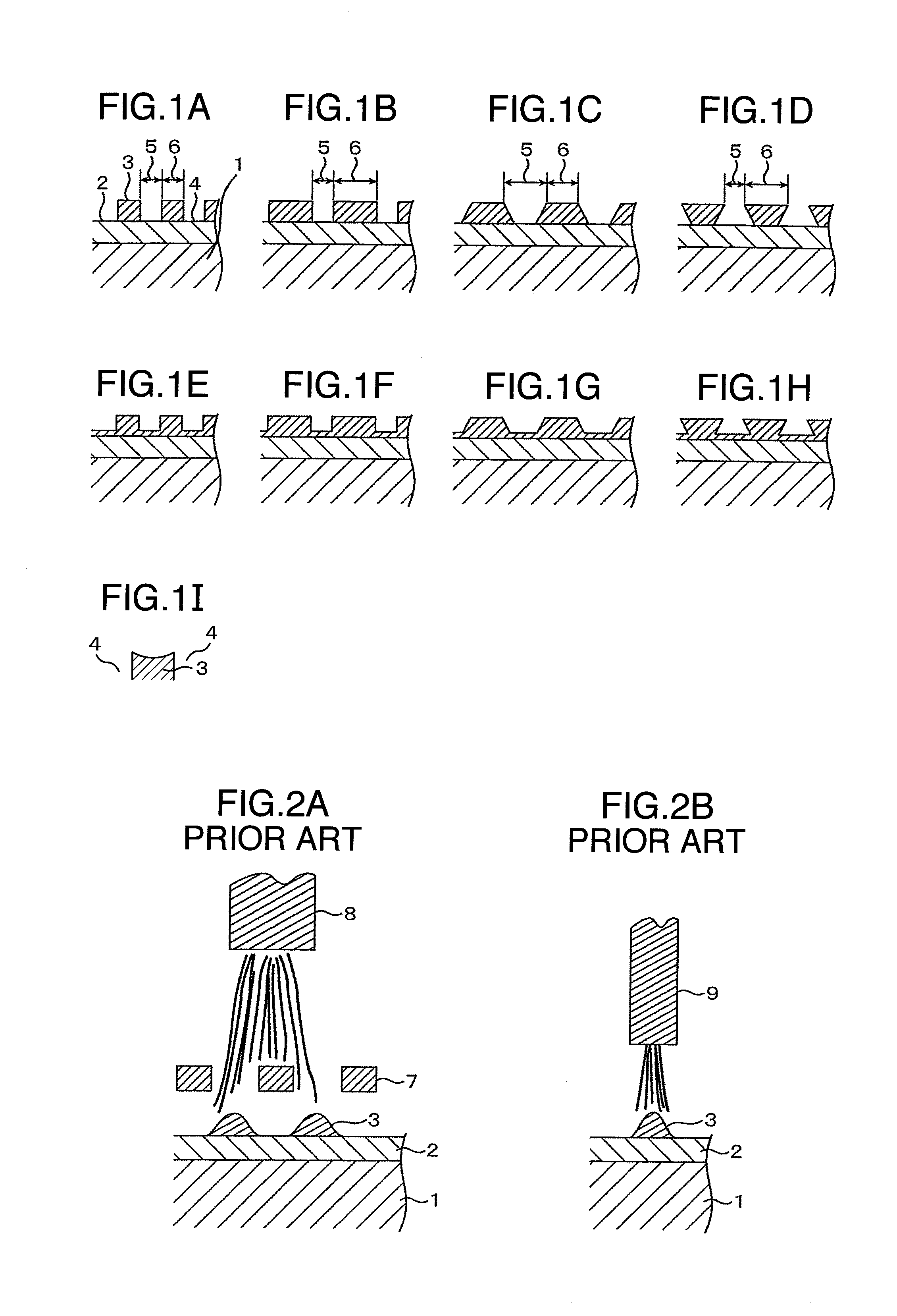
[0046]FIG. 1C shows a schematic sectional view of the abradable coating produced according to the method for forming the abradable coating of the present invention. FIG. 5 shows a shroud of an Ni group thermal resistant alloy used in the present example. The dimension is 75×145×18 mm. The abradable coating of the present invention was provided on a hot gas pass surface 13 of the shroud. On the base member, an MCrAlY alloy is thermally sprayed as the abradable metal layer (1 mm). As for the thermally spraying method, either plasma thermal spraying under a reduced pressure atmosphere, or high speed gas thermal spraying can be adopted. In the present example, a CoNiCrAlY alloy was thermally sprayed by plasma thermal spraying under a reduced pressure atmosphere. The thermally sprayed film thickness is 1.0 mm. The thermally spraying conditions are Ar—H2 gas, plasma output of 40 kW, a thermal spraying distance of 250 mm and a powder feed amount of 60 g / min with use of a METCO 9 MB gun, an...
example 2
[0047]With the thermal sprayed materials and the thermal spraying conditions similar to those of example 1, metal abradable layers and ceramic abradable layers were formed on the shroud of FIG. 5 shown in example 1, and slit grooves were formed by machining work. In the present example, slit groove working was carried out with use of a cutting grindstone. For the ceramic abradable layers, work of the slit grooves of 2 mm with the rectangle width of 2 mm was performed, and the rectangular ceramic abradable layers with square sections of FIG. 1B were formed, and slits grooves in the shapes similar to FIGS. 6A and 6B were formed. In contrast with such abradable coatings of the present invention, a ceramic abradable layer was formed with use of masking according to the method of JP-A-2006-36632, as in example 1. In this case, the section of the ceramic abradable layer was conical as in FIG. 2A. As a result that the thermal cycle test repeating holding 1 h heating at 1000° C. cooling as ...
example 3
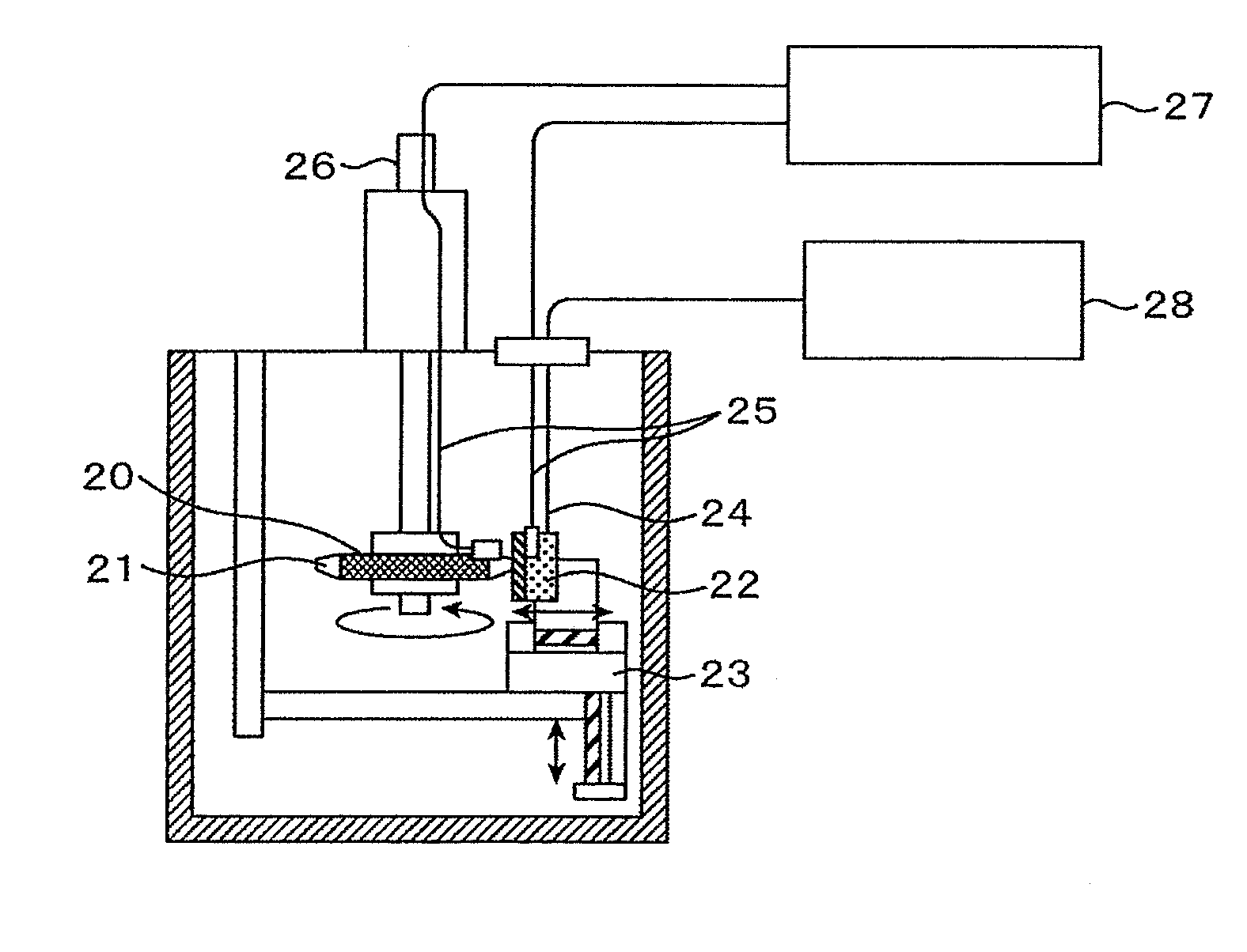
[0048]According to the similar method to example 1, the abradable coating according to the method for forming the abradable coating of the present invention was produced, and the abradable property test by high-speed rotation was carried out. FIG. 7 shows a test configuration diagram, and in the test, a test piece 22 mounted to a traverse device 23 is pressed against a tip end of a test blade 21 mounted to a test rotor 20 (φ200 mm) which is rotating at a high speed. The blade portion of the test blade has a blade length of 22 mm, a blade width of 20 mm and a blade thickness of 6 mm, and the test piece provided with the abradable coating of the present invention is a flat plate of 60×60 mm with a thickness of 40 mm. The test machine is configured by a thermocouple 24 for measuring the temperature of the test piece, strain gauge measuring lines 25 for measuring strain, a slip ring 26 for the measuring lines, a strain measuring section 27, and a temperature measuring section 28. The ab...
PUM
| Property | Measurement | Unit |
|---|---|---|
| width | aaaaa | aaaaa |
| temperature | aaaaa | aaaaa |
| temperature | aaaaa | aaaaa |
Abstract
Description
Claims
Application Information