Lithium Deposited Anode for a Lithium Second Battery and Its Manufacturing Method

Inactive Publication Date: 2012-05-17
KOREA UNIV RES & BUSINESS FOUND
View PDF5 Cites 33 Cited by
  • Summary
  • Abstract
  • Description
  • Claims
  • Application Information

AI Technical Summary

Benefits of technology

[0021]A lithium deposited anode for a lithium secondary battery according to the present invention limits dendrite growth only inside the concave portion of the silicon substrate where micro-size concave-convex patterns are formed. It is thus

Problems solved by technology

However, dendrite grows on the surface of the lithium metal while being charged and may be precipitated out while being discharged in this case.
Further, it may reach the opposite cathode through a separator during continuous charging•discharging processes, which may cause internal short and thus deteriorate battery capacity and charge•discharge efficiency.
When lithium itself is used as an anode material, maximum number of the charge•discharge cycle is only about dozens of times and it is far inferior in terms of total energy storage.
However, a carbon material such as graphite, carbon and the like, which may greatly increase charge and discharge cycle, even though it has low 1-cycle capacit

Method used


Image

  • Lithium Deposited Anode for a Lithium Second Battery and Its Manufacturing Method
  • Lithium Deposited Anode for a Lithium Second Battery and Its Manufacturing Method
  • Lithium Deposited Anode for a Lithium Second Battery and Its Manufacturing Method

Examples


Example

Example 1

Preparation of a Lithium Deposited Anode

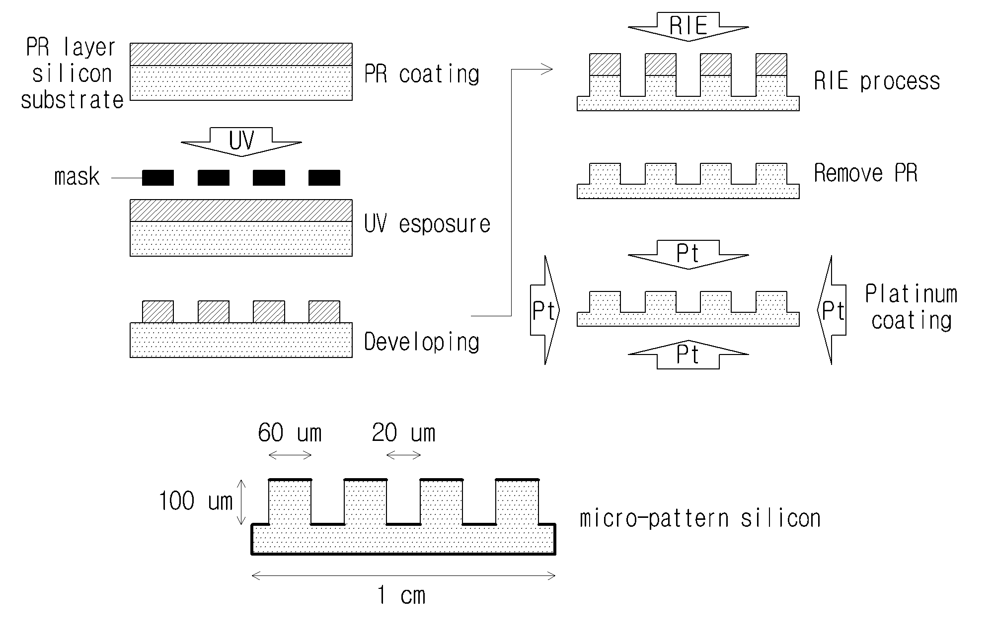
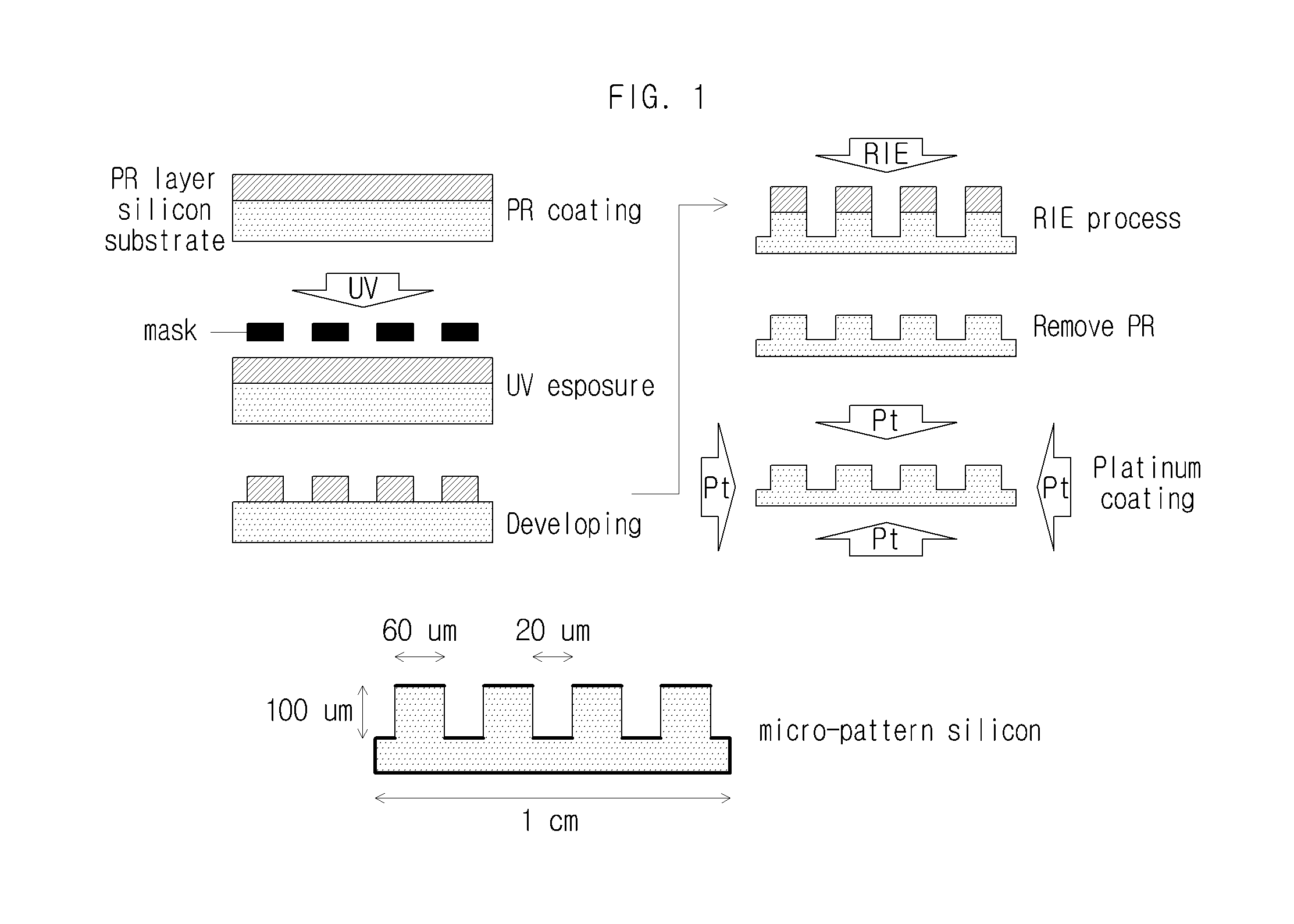
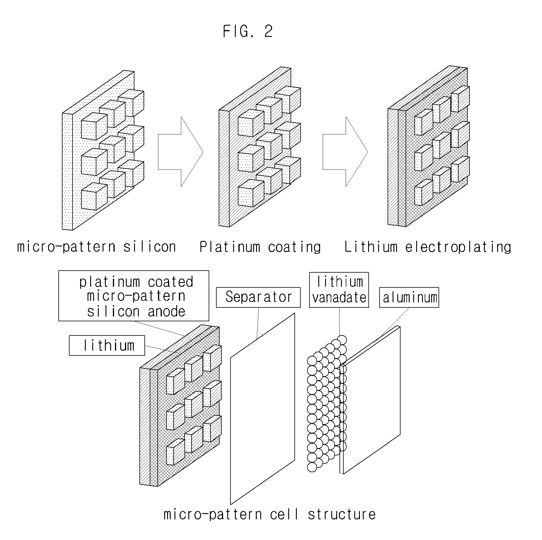
[0040]A positive photoresist (PR) was coated on the surface of a silicon substrate by employing a spin coating method. A photo-mask was closely placed to the surface of a silicon substrate and then it was exposed under UV. UV exposed PR was dissolved faster in a developing solution than UV unexposed PR. Micro patterns were formed on the surface of a silicon substrate, where the PR was coated, by reactive ion etching process. The remaining PR was then removed using a liquid resist stripping solution. The micro-size concave-convex patterns formed on the silicon substrate had 60 μm of width, 100 μm of depth and 20 μm of distance between convex portions. The concave-convex patterns-formed silicon substrate was cut in 1 cm2. Then platinum was coated on the micro-patterned surface of a silicon substrate by employing sputtering method and lithium was electroplated thereon. Here, even though platinum was coated over the entire surface of the ...

Example

Example 2

Preparation of a Cathode

[0041]A cathode was prepared using slurry including 80 wt % lithium trivanadate (LiV3O8), denka black as a conductive material and 5 wt % polyvinylidene fluoride (PVDF) as a binder. All materials were dissolved in N-methyl-2-pyrrolidone (NMP) and casted in aluminum foil pieces. LVO was powder having 10 μm of an average particle diameter. The cathode was dried at 120° C. for 1 hour under vacuum. Amount of LVO powder was 3.9 mg and theoretical capacity of the LVO cathode was determined to be about 1.1 mAh.

Example

Example 3

Preparation of a Lithium Secondary Battery

[0042]A lithium secondary battery was prepared by using standard coin cell (CR2032) type. An electrolyte was a solution mixed in 1:1:1 volume ratio of ethylene carbonate (EC):dimethyl carbonate (DMC):ethyl methyl carbonate (EMC). Coin cell was prepared in a glove box charged with Ar gas. A micro-size concave-convex patterns-formed silicon anode / LVO cell is shown in FIG. 2.


PUM


Abstract

The present invention relates to a lithium deposited anode for a lithium secondary battery and a method for preparing the same, and more particularly, to an anode suitable for a lithium secondary battery which limits dendrite growth only inside the concave portion of the silicon substrate during a battery is charged/discharged by depositing lithium as an active material only on the deeply caved concave portion of an anode current collector of which a micro-size patterned silicon substrate has conductivity provided by a metal, and its manufacturing method.

Description

TECHNICAL FIELD[0001]The present invention relates to a lithium deposited anode for a lithium secondary battery and a method for preparing the same, and more particularly, to an anode suitable for a lithium secondary battery which limits dendrite growth only inside the concave portion of the silicon substrate during a battery is charged / discharged by depositing lithium as an active material only on the deeply caved concave portion of an anode current collector of which a micro-size patterned silicon substrate has conductivity provided by a metal, and its manufacturing method.BACKGROUND[0002]A great deal of development research is currently under way on secondary batteries used as a power source in response to demands for mobile wireless devices such as mobile phones, portable computers, and camcorders with lighter weight and greater capabilities. Examples of such secondary batteries are nickel cadmium batteries, nickel hydrogen batteries, nickel zinc batteries and lithium secondary ...

Claims


Application Information

Patent Timeline
IPC IPC(8): H01M4/58B05D5/12G03F7/20H01M4/1395
CPCH01M4/661H01M4/0404Y02E60/10
Inventor YOON, WOO-YOUNGLEE, HEONJIN, DAE-GUN
Owner KOREA UNIV RES & BUSINESS FOUND
Why Eureka
Try Eureka