Method for the Spatially Resolved Measurement of Parameters in a Cross Section of a Beam Bundle of High-Energy Radiation of High Intensity

Inactive Publication Date: 2012-06-07
USHIO DENKI KK
View PDF5 Cites 23 Cited by
  • Summary
  • Abstract
  • Description
  • Claims
  • Application Information

AI Technical Summary

Benefits of technology

[0022]To this end, the invention provides that virtually the entire cross section of the beam bundle is shaded, and spatially narrowly defined openings of variable position permit a systematic measurement of partial beam bundles within the cross section of the beam bundle.
[0023]The reduction in intensity is achieved on the one hand in that the shading element is positioned in a convergent or divergent region of the beam bundle near an optical node, which can be the point source itself or an image of the source (conjugate source location or intermediate focus), and the measuring device (detector) is arranged at a large distance from the latter (use of the inverse square law or 1/r2 law). Accordingly, in the partial beam bundle which is formed, the intensity decreases with increasing distance from the shading element so that a measuring device arranged downstream in the beam path of the partial beam bundle can be outfitted with any conventional detectors in spite of very high power of the radiation source and very high intensity in the beam bundle to be measured. The shading element is arranged at, but not in, an optical node. A reduction in the intensity of the partial beam bundle passing the opening is preferably achieved by arranging the shading element in a divergent portion of the beam bundle.
[0024]On the other hand, the reduction in intensity of the original beam bundle also relies upon the additional diffraction and scattering of the partial beam bundle passing through the opening.
[0025]The separation of the beam bundle to be measured into partial beam bundles is carried out in that a movement of at least one opening of the element shading the entire cross section of the beam bundle, which movement is not defined concentric to the axis of the beam bundle, implements a systematic scanning (raster scan) of the

Problems solved by technology

Depending on the way in which the sensors operate, the characteristic passes after a certain value of the input signal into a saturation state which is not suitable for measuring purposes.
When sensors are used for measuring purposes of this kind, e.g., for soft X-ray radiation (EUV), the high radiation energies and intensities quickly lead to saturation or even destruction, e.g., due to high heat development in the sensors.
The use of optical

Method used


Image

  • Method for the Spatially Resolved Measurement of Parameters in a Cross Section of a Beam Bundle of High-Energy Radiation of High Intensity
  • Method for the Spatially Resolved Measurement of Parameters in a Cross Section of a Beam Bundle of High-Energy Radiation of High Intensity
  • Method for the Spatially Resolved Measurement of Parameters in a Cross Section of a Beam Bundle of High-Energy Radiation of High Intensity

Examples


Embodiment Construction

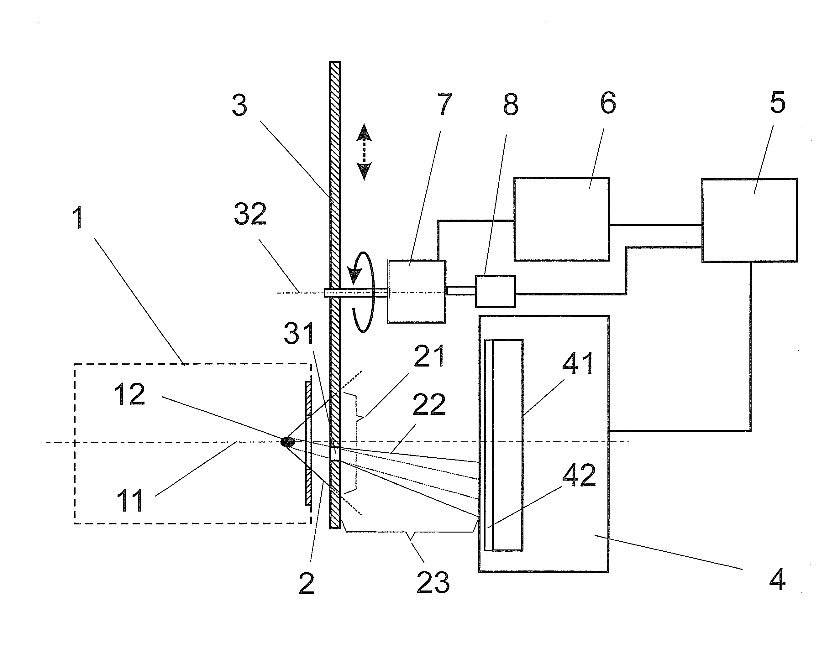
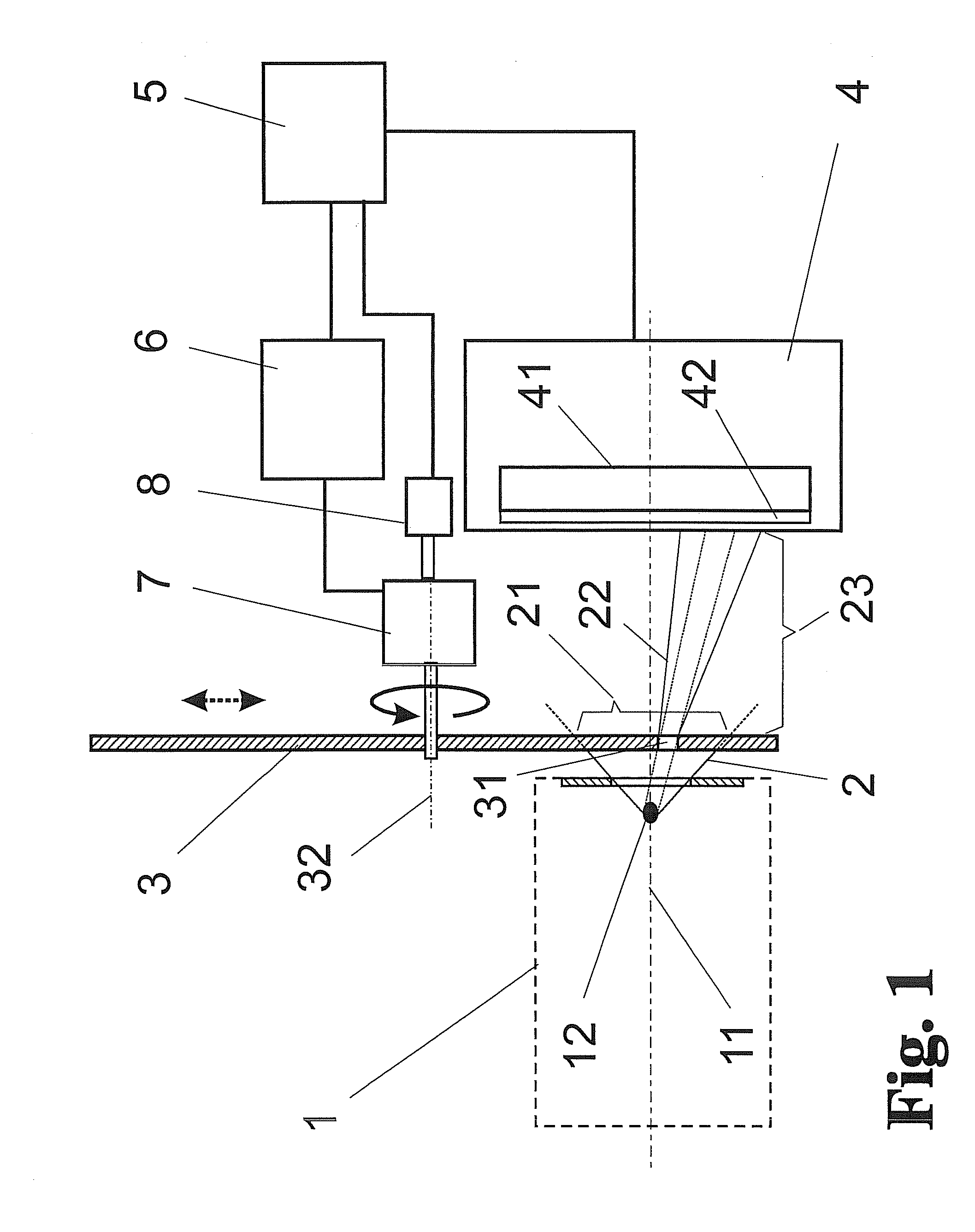
[0057]The method will be described with reference to the schematic construction shown in FIG. 1.

[0058]In the present method, a spatially limited bundle of high-energy radiation which is emitted by a radiation source 1 and which has an intensity (beam bundle 2) is measured with respect to its radiation characteristics (e.g., a spatial intensity distribution) over the beam cross section.

[0059]Radiation is emitted by the radiation source 1 (e.g., an EUV radiation source with a 13.5-nm working wavelength) along an optical axis 11 as a beam bundle 2 in the form of a spatially limited radiation cone, assumed for the sake of simplicity, which is possibly also focused through a collector 15 (shown only in FIG. 4) and is available for a measurement of beam parameters in its cross section 21.

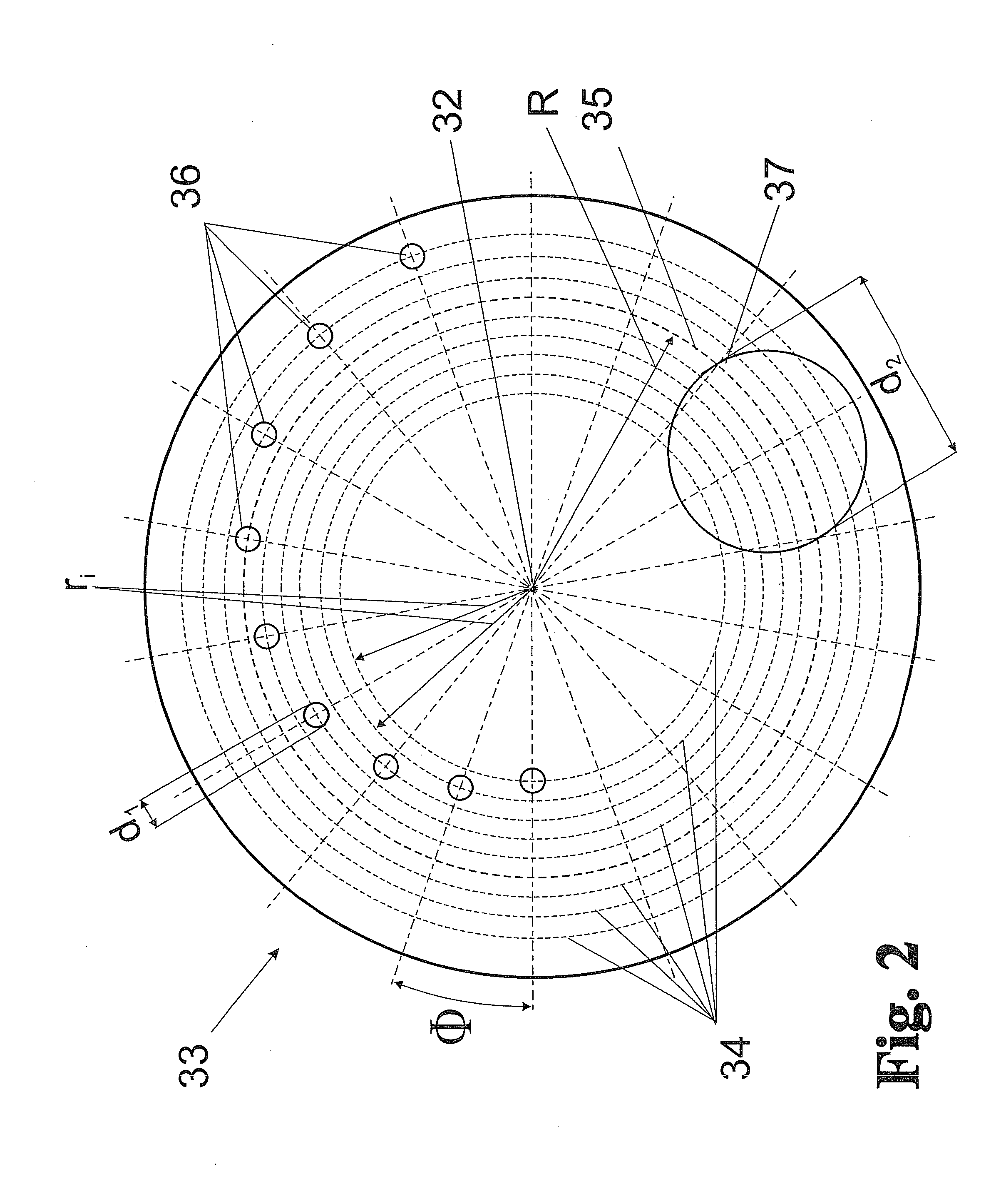
[0060]A shading element 3 is positioned in the beam bundle 2 following a source location 12 (the original or an optically conjugate source location) and is arranged in the immediate vicinity of the source...


PUM


Abstract

The invention is directed to methods and arrangements for spatial acquisition of measurement data over the cross section of a bundle of high-energy, high-intensity radiation. The object of finding a novel possibility for radiation measurement within the cross section of a beam bundle of high intensity which acquires highly spatially resolved measurement data without impairment of the measuring accuracy through saturation or degradation of the detectors is met according to the invention in that the entire cross section of the beam bundle is imaged on a shading element, the cross section is separated successively into partial beam bundles having reduced cross section and reduced intensity through movement of at least one opening, and measurement values of the partial beam bundles passing the opening are acquired so as to be associated temporally and spatially with the positions of the opening and are stored.

Description

RELATED APPLICATIONS[0001]This application claims priority to German Patent Application No. DE 10 2010 053 323.8, filed Dec. 2, 2010, which is incorporated herein by reference in its entirety.FIELD OF THE INVENTION[0002]The invention is directed to a method and an arrangement for spatial acquisition of measurement data (parameters) over the cross section of a bundle of high-energy, high-intensity radiation. It is preferably used in the measurement of high-energy beam bundles for the machining of workpieces to prepare spatial profiles of acquired radiation parameters.[0003]High-energy radiation, e.g., laser radiation, extreme ultraviolet (EUV) radiation, or particle radiation (electron beams or ion beams), is increasingly used for non-contact machining of workpieces such as, for example, semiconductor wafers which are structured by means of lithography processes. For efficient use of high-energy radiation of this kind, it is very important to measure particularly parameters such as t...

Claims


Application Information

Patent Timeline
IPC IPC(8): G01T1/20G01T1/00
CPCG01J1/0437G01J1/58G01J1/4257
Inventor MISSALLA, THOMASSCHUERMANN, MAX CHRISTIANBOLSHUKHIN, DENISTKACHENKO, BORIS
Owner USHIO DENKI KK
Why Eureka
Try Eureka