Composite Spoolable Tube

a spoolable tube and composite technology, applied in the field of spoolable tubes, can solve the problems of high economic cost, high risk to personnel, and fracture of steel coiled tubes, and achieve the effects of reducing the strain on the energy conductor, and easy damag

Inactive Publication Date: 2012-06-21
FIBERSPAR
View PDF3 Cites 35 Cited by
  • Summary
  • Abstract
  • Description
  • Claims
  • Application Information

AI Technical Summary

Benefits of technology

[0034]Energy conductors commonly have low strain capability and thus can be damaged easily by large deformations such as those imposed by bending. These energy conductors are thus oriented in a helical direction relative to the longitudinal axis of the tube. This orientation minimizes the strain on the energy conductor when the tube bends. In an alternative aspect of the invention, the energy conductors can be aligned axially along the length of the tube. Two axially aligned energy conductors that are diametrically opposed along the length of the tube can provide a bending moment along the length of the composite tube, such that the conductors are located on a neutral bending axis that minimizes bending strains on the conductors.
[0035]Various embodiments of the invention exist which include one or more aspects and features of the invention described ab

Problems solved by technology

Unfortunately, the repeated spooling and use of steel coiled tubing causes fatigue damage that can suddenly cause the steel coiled tubing to fracture and fail.
The hazards of operating steel coiled tubing, i.e. risk to personnel and high economic cost resulting from down time needed to retrieve the broken tubing sections, forces steel coiled tubing to be retired after a relatively few number of trips into a well.
Tube expansion results in reduced wall thickness with the associated reduction in the pressure carrying capability of the steel coiled tubing.
Accordingly, higher pressure and continuous flexing typically reduces the steel tube's integrity and service life.
The repeated bending of steel coiled tubing into and out of plastic deformation induces irreparable damage to the steel tube body leading to low-cycle fatigue failure.
Additionally, when steel coiled tubing is exposed to high internal pressures and bending loads, the isotropic steel is subjected to high triaxial stresses imposed by the added pressure and bending loads.
The high triaxi

Method used


Image

  • Composite Spoolable Tube
  • Composite Spoolable Tube
  • Composite Spoolable Tube

Examples


Embodiment Construction

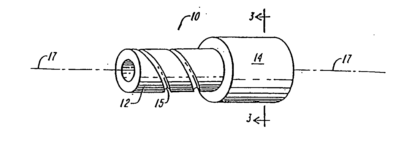
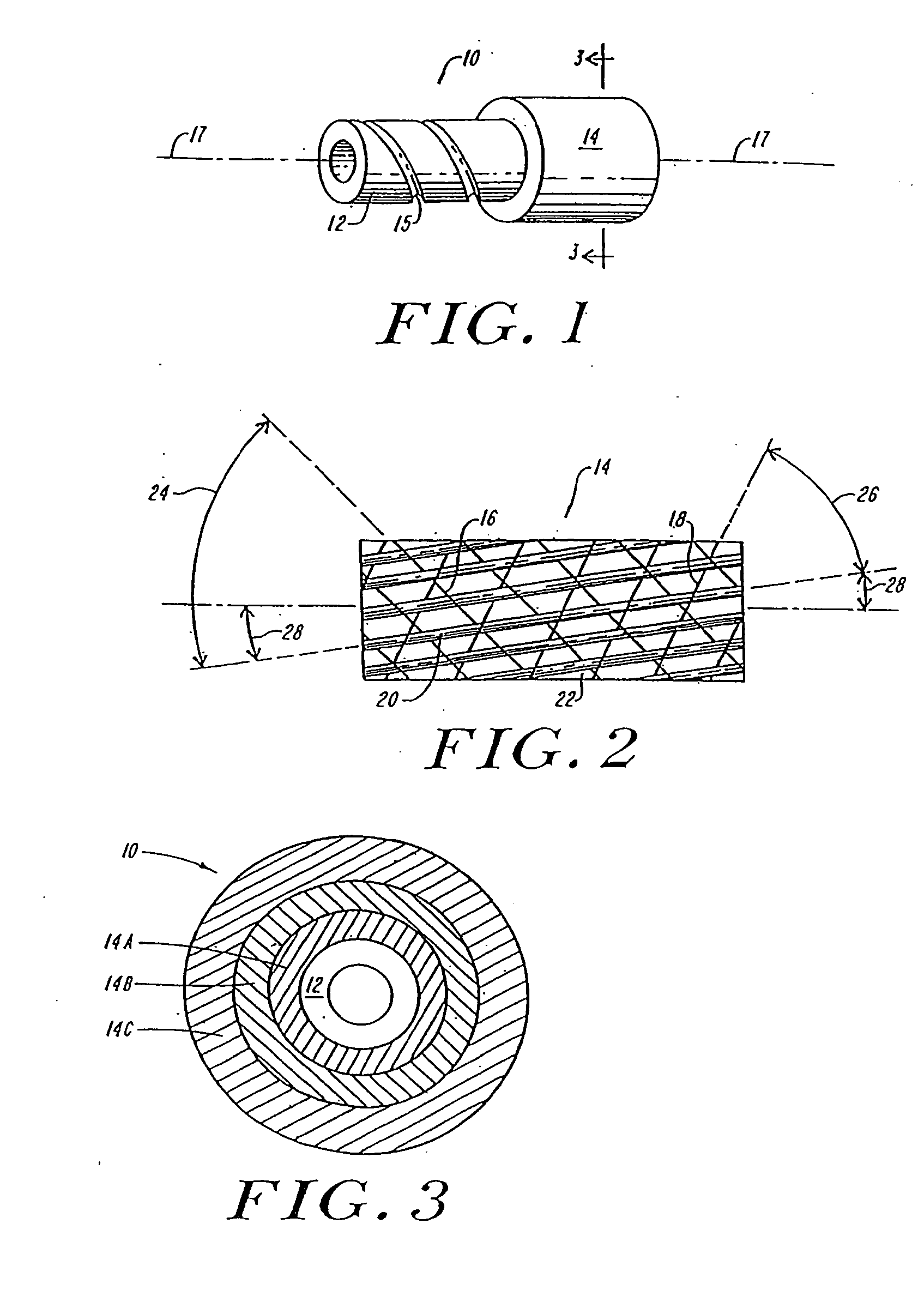
[0051]Composite fibers (graphite, Kevlar, fiberglass, boron, etc.) have numerous assets including high strength, high stiffness, light-weight, etc., however, the stress strain response of composite fibers is linear to failure and therefore non ductile. Composite coiled tubing must therefore address the strain limitations in another manner, i.e., by providing a construction to meet the requirements with a near elastic response or with large deformations of the matrix. Such a composite arrangement must have high resistance to bending stresses and internal pressure and external pressure. It must also have high axial stiffness, high tensile and compressive strength and be resistant to shear stress. All of these properties are combined in the composite tubular member of the invention to provide a coiled tubing which can be bent to a radius compatible with winding onto a reasonable size spool.

[0052]P. K. Mallick in the text book entitled Fiber-Reinforced Composites, Materials, manufacturi...


PUM


Abstract

A spoolable composite tube capable of being spooled onto a reel for storage and for use in oil field applications. The spoolable tube exhibits unique anistropic characteristics that provide improved burst and collapse pressures, increased tensile strength, compression strength, and load carrying capacity, while still remaining sufficiently bendable to be spooled onto a reel in an open bore configuration. The spoolable composite tube can include an inner liner, an interface layer, fiber composite layers, a pressure barrier layer, and an outer protective layer. The fiber composite layers can have a unique triaxial braid structure.

Description

RELATED APPLICATIONS [0001]The current application is a continuation of U.S. patent application Ser. No. 12 / 629,683, which is a continuation of U.S. patent application Ser. No. 10 / 997,453, filed Nov. 24, 2004, now U.S. Pat. No. 7,647,948; which is a continuation of U.S. patent application Ser. No. 10 / 460,768, filed Jun. 12, 2003, now U.S. Pat. No. 6,857,452; which is a continuation of U.S. patent application Ser. No. 10 / 041,247, filed Jan. 8, 2002, now U.S. Pat. No. 6,604,550; which is a continuation of U.S. patent application Ser. No. 09 / 875,561 filed Jun. 6, 2001, now U.S. Pat. No. 6,357,485; which is a continuation of U.S. patent application Ser. No. 09 / 597,201 filed Jun. 20, 2000, now U.S. Pat. No. 6,286,558; which is a continuation of U.S. patent application Ser. No. 09 / 295,289 filed Apr. 20, 1999, now U.S. Pat. No. 6,148,866; which is a continuation of U.S. patent application Ser. No. 08 / 804,790, filed Feb. 24, 1997, now U.S. Pat. No. 5,921,285; which is a continuation-in-part...

Claims


Application Information

Patent Timeline
IPC IPC(8): G02B6/44F16L11/127H01B7/17F16L11/04E21B17/20F16L9/12F16L9/147F16L9/19F16L11/08F16L11/14
CPCE21B17/20E21B17/203E21B17/206F16L9/12F16L11/14F16L9/147F16L9/19F16L11/085F16L11/127F16L9/125
Inventor QUIGLEY, PETER A.NOLET, STEPHEN C.WILLIAMS, JERRY G.
Owner FIBERSPAR
Why Eureka
Try Eureka