Zero emission steam generation process

a technology of steam generation and zero emission, applied in the direction of indirect carbon dioxide mitigation, solid fuel combustion, lighting and heating apparatus, etc., can solve the problems of increasing capital, maintenance, operating costs, environmental impact, reducing the efficiency of heaters and coolers, and reducing the capital and operating costs of thermal oil recovery processes. , to achieve the effect of reducing the capital and operating costs of the thermal oil recovery process

Inactive Publication Date: 2012-06-28
PAXTON CORP +2
View PDF7 Cites 12 Cited by
  • Summary
  • Abstract
  • Description
  • Claims
  • Application Information

AI Technical Summary

Benefits of technology

[0016]Specifically, the process uses the apparatus, designed as a gas generator, as a new concept of the process vessel to use subterranean waters, which are co-produced with oil, directly for steam without softening or treating prior to boiling. Thermal recovery includes, but not limited to, Steam Assisted Gravity Drainage (SAGD), Cyclic Steam Stimulation (CSS), Steam Flooding, or combined steam-additive processes where the additive can be one or more of non-condensable gas, solvent, or surfactant. In addition the process captures all combustion gases produced and injects steam and combustion gasses underground simultaneously, removing the ongoing requirement for make up water in thermal oil recovery.
[0038]According to a preferred embodiment, the feed water includes untreated subterranean water, which is co-produced with oil production. The ability to use this untreated produced water will result in following advantages:
[0039]It will remove the ongoing requirement for additional water into a thermal oil recovery process such as, but not limited to, Steam Assisted Gravity Drainage (SAGD), Cyclic Steam Stimulation (CSS), or Steam Flooding, or other recovery processes that start with steam injection e.g. in situ combustion. By capturing the water of combustion, once the production process is stable, no further water will be required.
[0040]It will increase the thermal efficiency of the process. By capturing heat lost to stack emissions and further piping losses, thermal efficiencies can increase by more than 10%.
[0041]It will reduce thermal oil recovery process capital and operating costs by up to 50%, through the complete removal of water treatment equipment.

Problems solved by technology

Dealing with the impurities result in increased capital, maintenance, operating cost, and environmental impact.
Usually in a traditional thermal oil recovery system the water treatment process, accounts for up to 50% of the operating costs.
Moreover, all thermal recovery projects have ongoing water requirements to make up water losses and water treating blow down.
Traditionally heating / cooling processes take place in heat exchanger vessels and devices, which have one common deficiency: all those vessels and devices used in all industries maintain a separation between reactive substances and the targets of heating or cooling.
This separation reduces the efficiency of the heaters and coolers substantially.
In all those cases the methods of capturing carbon dioxide for use in enhanced hydrocarbon recovery are complicated and capital intensive.
In thermal recovery however, free gas in a reservoir may lower the in-situ reservoir temperature, which in turn will reduce oil recovery.

Method used


Image

  • Zero emission steam generation process
  • Zero emission steam generation process
  • Zero emission steam generation process

Examples


first embodiment

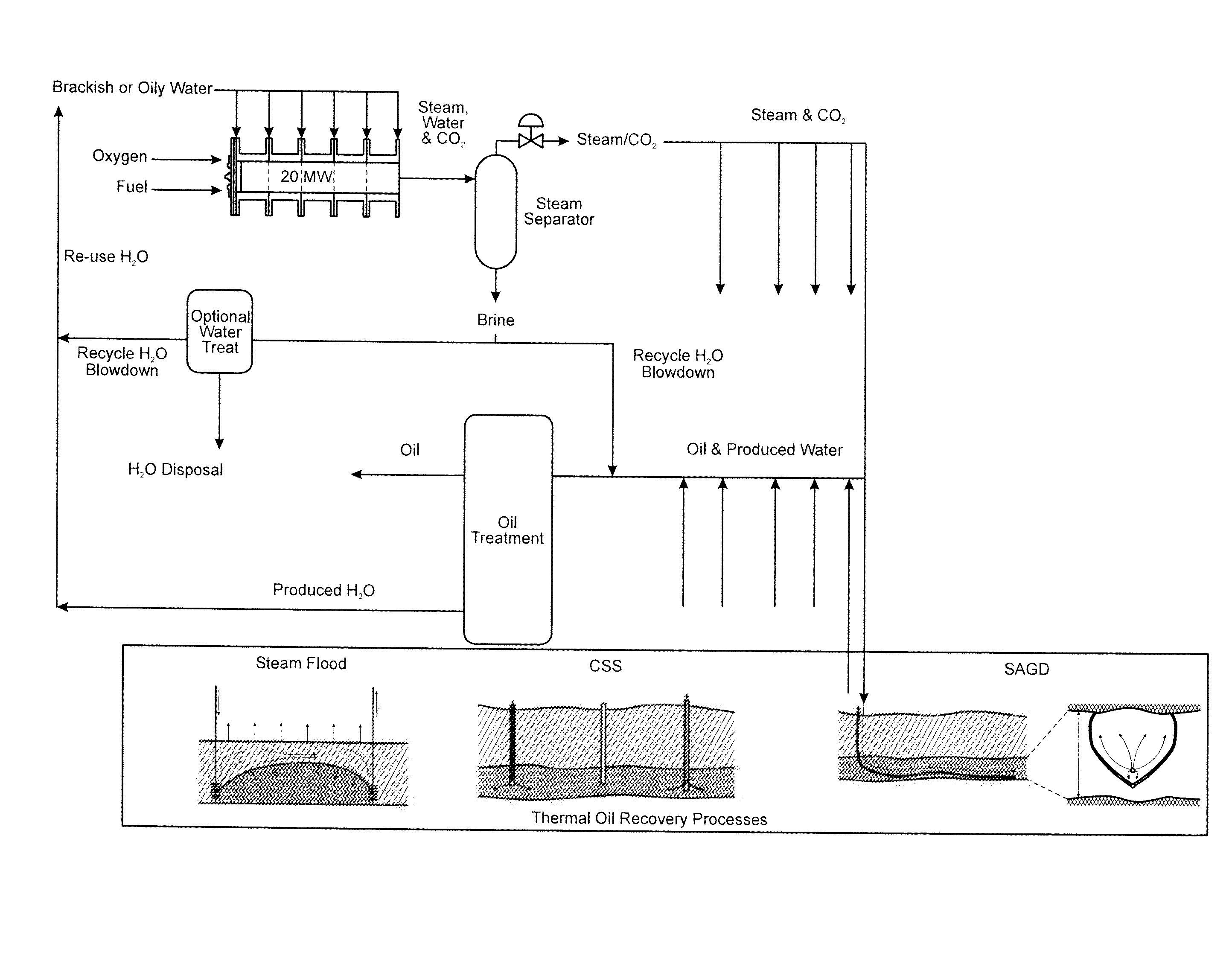
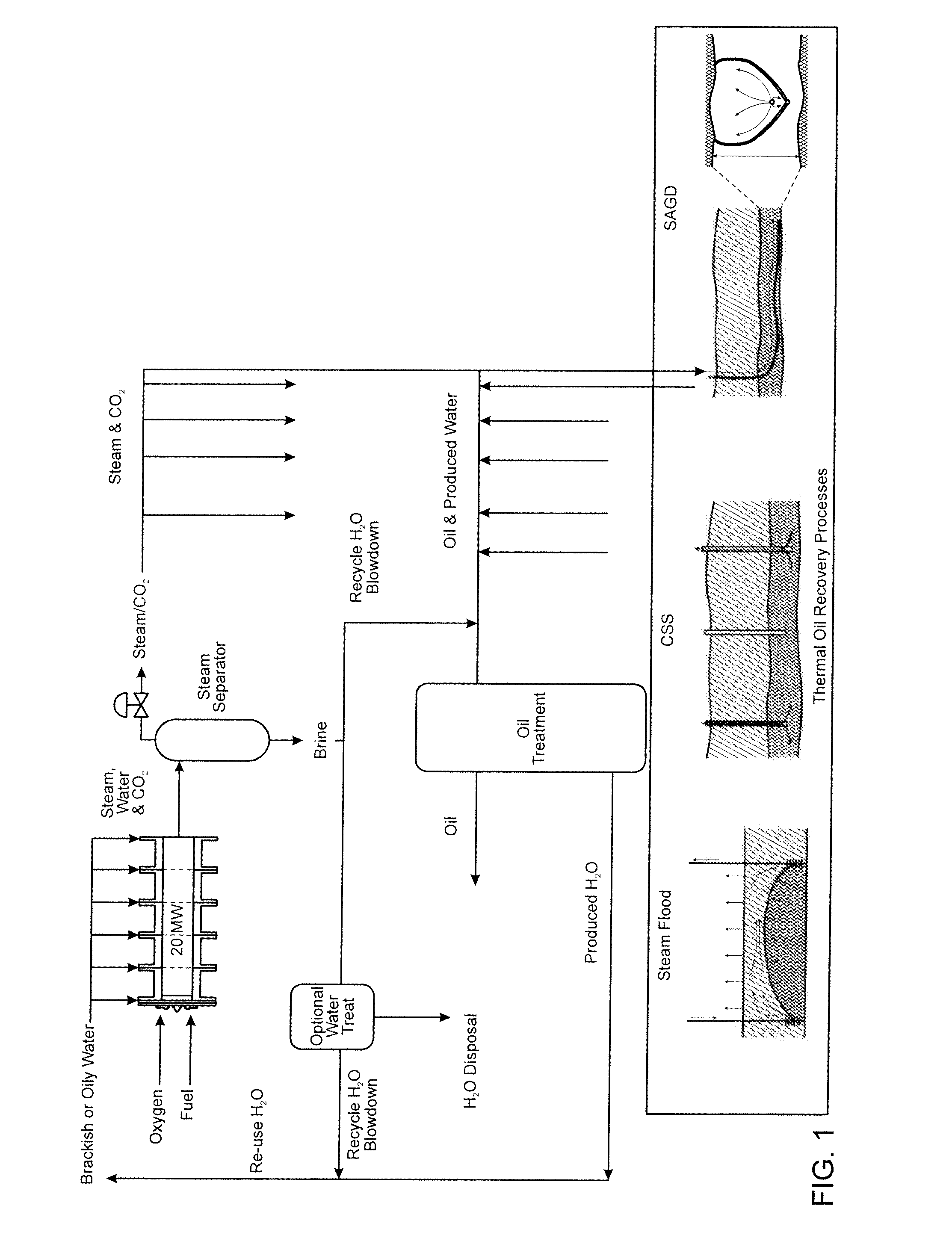
[0071]In this new process, shown in FIG. 1, the oxy-fuel steam generator directly mixes fuel such as natural gas, oxygen and feed water to generate a steam, liquid water and carbon dioxide mixture. The fuel and the Oxygen are mixed and burned in the reaction chamber which also known as a combustion chamber of the flaming unit. The feed water is added directly to this reaction chamber into the mixture of the combustion gases while part of the impurities in the water takes part in the burning process while generating steam mixture.

[0072]The water in the inlet of the generator containing anywhere from 500 to 20,000 ppm dissolved solids. This is a substantial improvement, since the current industrial boilers have an upper limit to dissolved solids of up to 5,000 ppm. The steam generator output quality will be altered from 100% to under 60%, depending on the suspended solids present in the input water. Steam generator metallurgy will be altered to ensure corrosion will not occur in the b...

second embodiment

[0081]In a second embodiment, the process uses the steam generator and separator combinations directly at the remote well site (at satellite locations in the oil field) instead of conventional practice where they are located at a central plant. Fuel (e.g. natural gas), oxygen, and produced water are piped to the remote satellites where the steam generators can be sited. In this embodiment, the location is no longer tied to an extensive and expensive water treatment apparatus. The suggested capacity for the remote oxy-fuel steam generator is about 20 MW. However, the sizes and capacities of those generators may vary according to the requirements of the industry.

third embodiment

[0082]In the invention, the oxy-fuel steam generator can use partially enriched air, with up to 10% remaining nitrogen content, instead of pure oxygen. The use of lower purity oxygen as the oxidizer may increase nitrogen oxides (NOx) in combustion gases, but since all combustion products are injected underground, there are no ill environmental effects.

[0083]FIG. 4 shows a conventional thermal oil process, with the water treatment block and water disposal and make-up streams highlighted. These water treatment process blocks have been required for all previous technologies because all previous thermal oil processes use either current industrial boilers, which have an upper limit to dissolved solids of up to 5,000 ppm with much lower thresholds for water hardness and silica, or have referenced operating conditions for direct fired boilers which require “dirty water” to still be below thresholds which require softening. Those process blocks are all eliminated in the proposed embodiment....


PUM


Abstract

This invention provides a new process to generate steam directly from untreated water produced simultaneously with thermally recovered crude oil, and to inject the steam and combustion products into a hydrocarbon reservoir to recover hydrocarbons and to sequester a portion of the carbon dioxide produced during the creation of steam. The invention removes the ongoing additional water requirements for thermal oil recovery and the need for surface treating of produced water for re-use, yielding improved process efficiencies, reduced environmental impact, and improved economic value.

Description

FIELD OF THE INVENTION[0001]The current invention pertains to an area of generating of steam for the thermal recovery of oil and bitumen from subsurface hydrocarbon reservoirs. Specifically, to the area of using an oxygen fuel combustor as a steam generator.BACKGROUND OF THE INVENTION[0002]Thermal oil recovery projects, including but not limited to Steam Assisted Gravity Drainage (SAGD), Cyclic Steam Stimulation (CSS), or Steam Flooding, or recovery processes that potentially start with steam injection (e.g. in situ combustion) utilize large amounts of water in the form of steam, to carry heat energy underground to mobilize the oil, heavy oil, or bitumen. This water, typically in a ratio of three or higher parts water to one part oil, is transported back to the surface with the oil. Previous processes have required extensive water treatment and handling to clean the water prior to it being re-used as boiler feed water. For example, water treatment can involve one or more of gravity ...

Claims


Application Information

Patent Timeline
Patent Type & Authority Applications(United States)
IPC IPC(8): F22B1/26F23L7/00
CPCF22B1/1853Y02E20/344
Inventor BUNIO, GARY L.GATES, IAN DONALDSUDLOW, PAULANDERSON, ROGER E.PROPP, MURRAY E.
Owner PAXTON CORP
Why Eureka
Try Eureka