Gas field ionization ion source and ion beam device

a technology of ion beam and ion source, which is applied in the direction of ion beam tubes, instruments, heat measurement, etc., can solve the problems of increasing the temperature of the emitter tip, difficult to provide an ion beam with high brightness, and difficult to obtain enough ion current, so as to achieve the effect of reducing the temperature of the tip of the emitter electrode and high brightness

Inactive Publication Date: 2012-08-09
HITACHI HIGH-TECH CORP
View PDF7 Cites 36 Cited by
  • Summary
  • Abstract
  • Description
  • Claims
  • Application Information

AI Technical Summary

Benefits of technology

[0020]According to the gas field ionization ion source of the present invention, the temperature of the tip of the emitter electrode can be decreased with the gas kept at high temperature. Accordingly, the temperature of the tip end of the emitter electrode can be decreased in order to obtain an ion beam with high brightness while the temperature of the gas is increased in order to emit heavy ions.

Problems solved by technology

However, since such a heavy gas generally has a high devaporization point (boiling point), the temperature of the gas needs to be increased sufficiently, which leads to an increase in the temperature of the emitter tip.
This makes it difficult to obtain enough ion current, so that it is difficult to provide an ion beam with high brightness.

Method used


Image

  • Gas field ionization ion source and ion beam device
  • Gas field ionization ion source and ion beam device
  • Gas field ionization ion source and ion beam device

Examples


embodiment 1

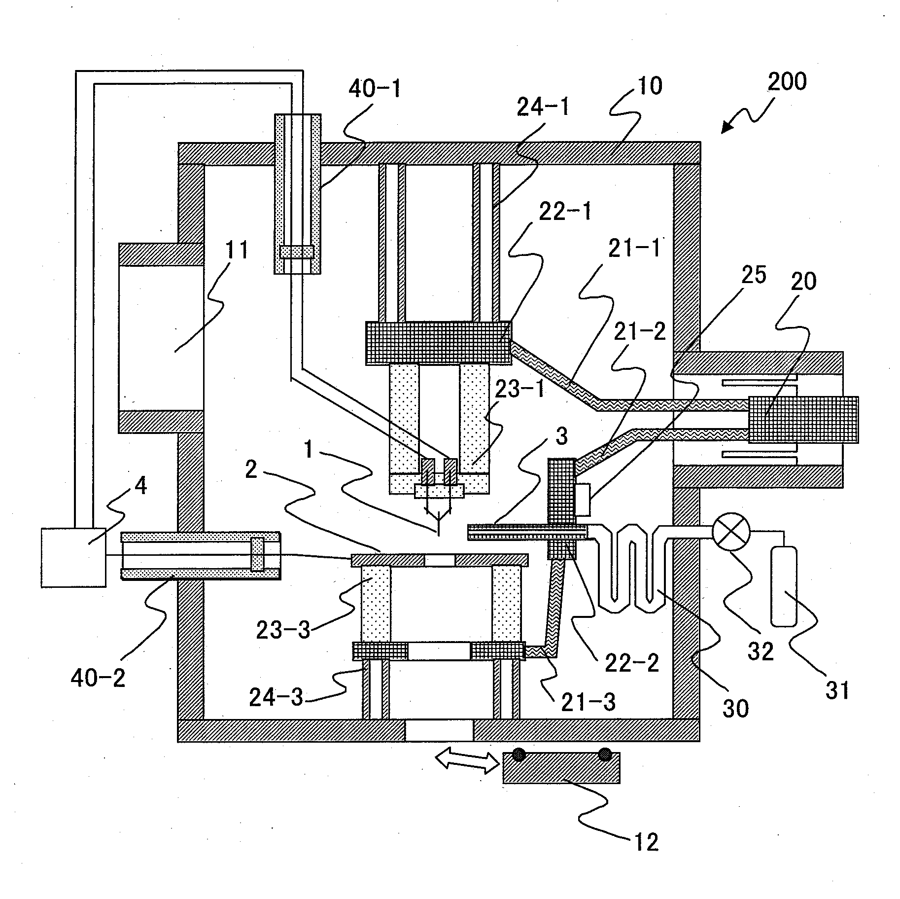
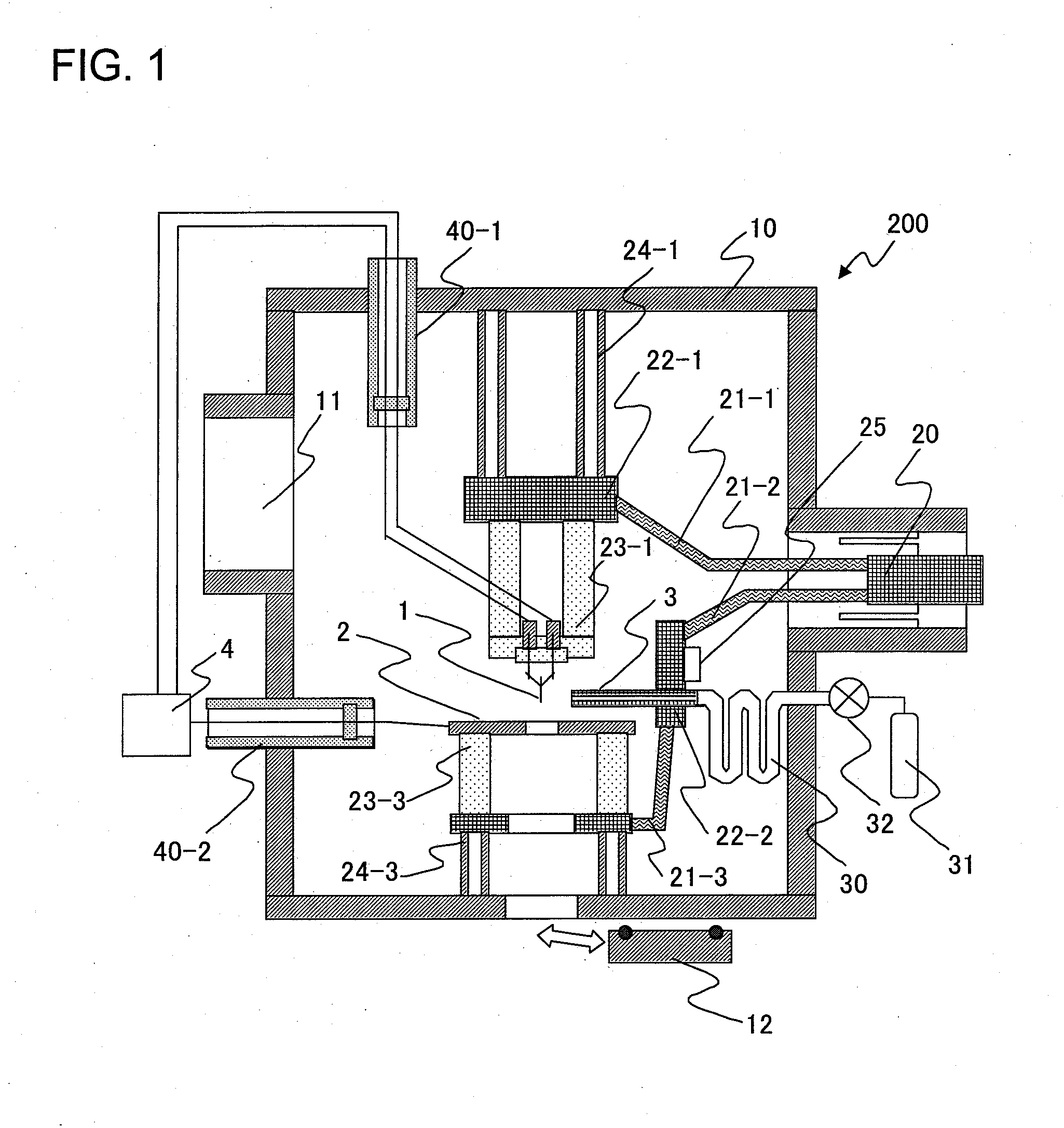
[0030]FIG. 1 is a cross-sectional view showing a configuration of an ion beam device 200 according to Embodiment 1. The ion beam device 200 includes a gas field ionization ion source (GFIS) and converging an ion beam emitted from the GFIS to irradiate a sample with the ion beam for observation or processing of the sample. Hereinafter, a description is given of constituent components shown in FIG. 1.

[0031]A vacuum vessel 10 is kept at ultrahigh vacuum of the 10−8 Pa range by an vacuum pumping system (not shown) connected to an exhaust port 11. If the ion beam device 200 is not connected to another device, the vacuum vessel 10 is closed by a valve 12.

[0032]In the vacuum vessel 10, an emitter tip 1 having a needle-like point and an extraction electrode 2 having an opening facing the tip end of the emitter tip 1 are placed. The emitter tip 1 requires an axis alignment mechanism but is not shown in the drawings to simplify the description.

[0033]A gas injection port part 3 of a gas supply...

embodiment 2

[0058]FIG. 4 is a schematic view showing a configuration of an ion beam device 200 according to Embodiment 2 of the present invention. The ion beam device 200 according to Embodiment 2 is a device in which the GFIS described in Embodiment 1 (indicated by reference numeral 100 in FIG. 4) is incorporated in a focused ion beam device manufactured for a conventional Ga-LMIS. A description is given of each configuration of FIG. 4 below.

[0059]An ion beam 5 emitted from the emitter tip 1 is converged by electrostatic lenses 102-1 and 102-2 to irradiate the sample 6. The irradiation position of the ion beam 5 on the sample 6 is adjusted by deflecting the ion beam 5 with deflectors 103-1 and 103-2.

[0060]Secondary electrons 7 generated from the sample 6 are detected by a secondary electron detector 104, and a secondary electron observation image in which signal intensity corresponds to the deflection intensity is formed by a display 110. The user can specify the position at which the ion beam...

embodiment 3

[0064]Embodiment 1 and 2 describe that a heavy ionic species is emitted with high brightness. On the other hand, before processing, observation of an SIM image and the like is carried out in order to determine the beam irradiation position. In this process, it is necessary to project the ion beam onto the sample. At this time, the ion beam can give extra processing damage to the sample. However, reducing the ion current or dose amount of ions for the purpose of reducing the processing damage includes a problem.

[0065]First, the angle at which ions are emitted from the GFIS is about one digit smaller than that in the case of the Ga-LMIS. Accordingly, even if the angle is limited, the ion current can be reduced only slightly. Moreover, if the SIM image is obtained with the dose amount of ions reduced, the positional accuracy is reduced due to noise.

[0066]In Embodiment 3 of the present invention, in order to solve the aforementioned problems, a description is given of a configuration an...


PUM


Abstract

Provided is a gas field ionization ion source capable of emitting heavy ions with high brightness which are suitable for processing a sample. The gas field ionization ion source according to the present invention includes a temperature controller individually controlling the temperature of the tip end of an emitter electrode (1) and the temperature of a gas injection port part (3) of a gas supply unit.

Description

TECHNICAL FIELD[0001]The present invention relates to a gas field ionization ion source and an ion beam device including the same.BACKGROUND ART[0002]Non-patent Document 1 listed below describes focused ion beam (abbreviated as FIB) devices each of which includes a gas field ionization ion source (abbreviated as GFIS) and uses gas ions of hydrogen (H2), helium (He), neon (Ne), or the like. Such gas FIB devices have an advantage of not contaminating samples with Ga unlike gallium (Ga: metal) FIB devices including liquid metal ion sources (abbreviated as LMISs) which are commonly used currently. In Non-patent Document 1, GFISs can form beams finer than Ga-FIB devices because gas ions extracted from the GFISs have narrow energy width and the ion generation source is small.[0003]Non-patent Documents 2 and 3 and Patent Document 1 listed below disclose that provision of a microprotrusion (emitter tip) to the tip end of the emitter of a GFIS or reduction of the number of atoms at the tip e...

Claims


Application Information

Patent Timeline
Patent Type & Authority Applications(United States)
IPC IPC(8): H01J3/14H01T23/00
CPCH01J27/26H01J37/08H01J2237/0807H01J2237/002H01J2237/006H01J37/3056
Inventor KAWANAMI, YOSHIMIISHITANI, TOHRU
Owner HITACHI HIGH-TECH CORP
Why Eureka
Try Eureka