Fiber electrode and fiber battery, method of fabricating the same, and fiber electrode and fiber battery fabrication apparatus

a technology of fiber electrodes and fabrication methods, which is applied in the field of fiber electrodes and fiber batteries, method of fabricating the same, and fiber electrodes and fiber battery fabrication apparatus, can solve the problems that the battery structure disclosed in patent literature 2 cannot realize high power, and the porous body has not been developed to a practical level. achieve the effect of efficiently fabricated, efficient fabricated, and efficient fabrication of fiber electrodes

Inactive Publication Date: 2012-08-23
KAWASAKI HEAVY IND LTD
View PDF10 Cites 22 Cited by
  • Summary
  • Abstract
  • Description
  • Claims
  • Application Information

AI Technical Summary

Benefits of technology

[0049]According to the fiber electrode fabrication method of the present invention, a large number of fiber electrodes can be efficiently fabricated at the same time from a large number of fibers while taking advantage of inherent characteristics of fiber electrodes.
[0050]According to the fiber battery fabrication method of the present invention, a high-power fiber battery can be efficiently fabricated by using a large number of fiber electrodes.
[0051]Moreover, the fiber battery fabrication apparatus and the fiber electrode fabrication apparatus of the present invention are suitable for efficiently fabricating fiber electrodes and a fiber battery.
[0052]In the fiber battery of the present inventi

Problems solved by technology

Although there are publicly known porous bodies having irregularity that are formed through mechanical processing, such porous bodies have not been developed to a practical level.
However, in the case of an aqueous electrolyte solution, the operating voltage is 1.2 V, which is low,

Method used


Image

  • Fiber electrode and fiber battery, method of fabricating the same, and fiber electrode and fiber battery fabrication apparatus
  • Fiber electrode and fiber battery, method of fabricating the same, and fiber electrode and fiber battery fabrication apparatus
  • Fiber electrode and fiber battery, method of fabricating the same, and fiber electrode and fiber battery fabrication apparatus

Examples


example 3

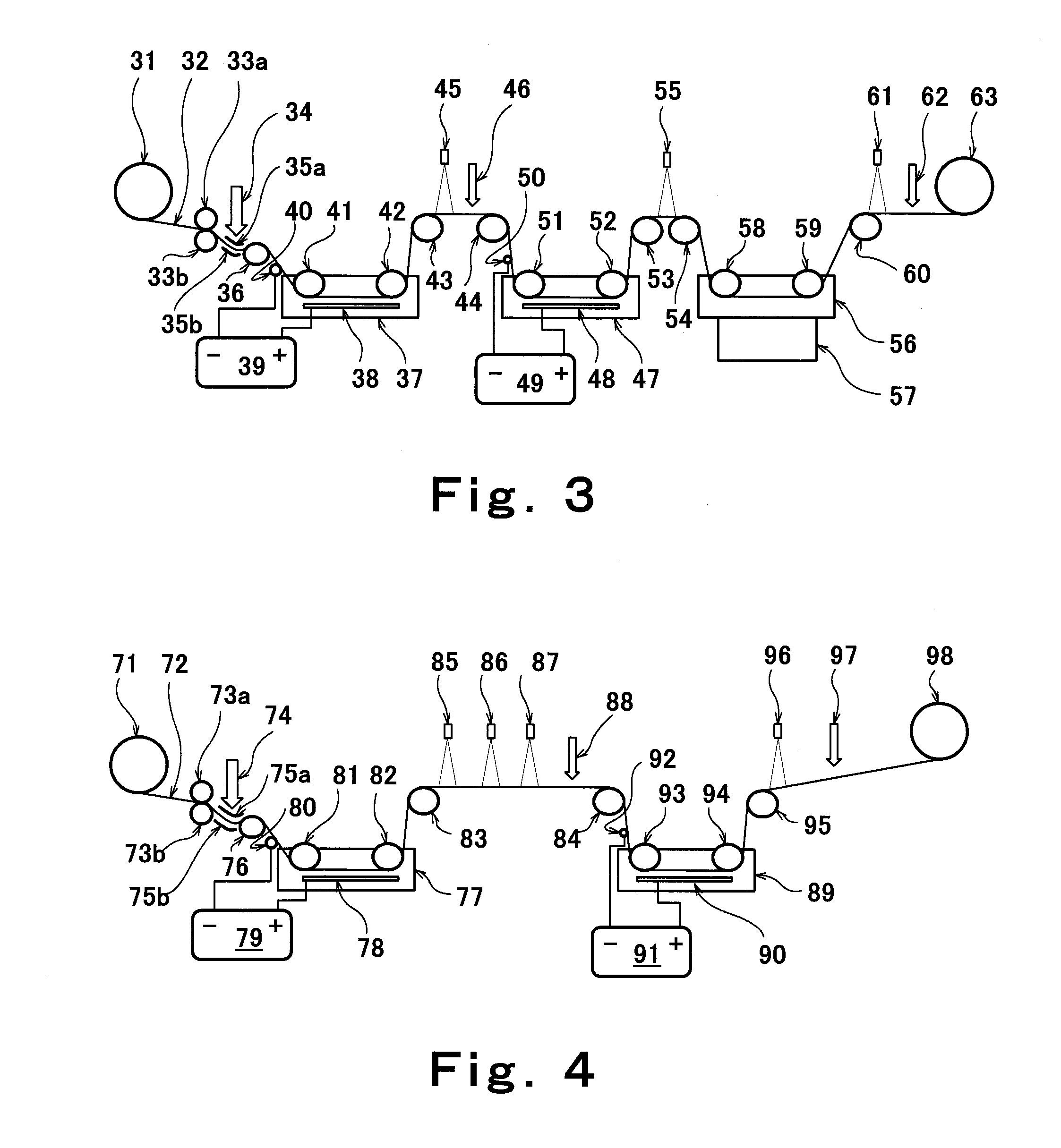
(4) Example 3 of Fiber Electrode Fabrication Method

[0131]FIG. 4 is a schematic structural diagram showing yet another example of the fiber electrode fabrication apparatus. A fibrous positive electrode for use in a lithium ion secondary battery was fabricated by using the fiber electrode fabrication apparatus as shown in FIG. 4. In FIG. 4, the reference sign 71 denotes a winding roller around which a carbon fiber tow 72 formed of 12000 PAN-based carbon fibers is wound in a rolled-up manner. The PAN-based carbon fiber tow 72 is unwound from the winding roller 71 and passes through a pair of upper and lower guide rollers 73a and 73b. Then, compressed air 74 compressed by a compressor (not shown) is blown against the carbon fiber tow 72. As a result, the carbon fiber tow is spread, so that the width thereof is increased from 1 cm, which is the original width, to 5 cm. The reference signs 75a and 75b denote air diffuser plates for diffusing the compressed air in the width direction of th...

example 4

(5) Example 4 of Fiber Electrode Fabrication Method

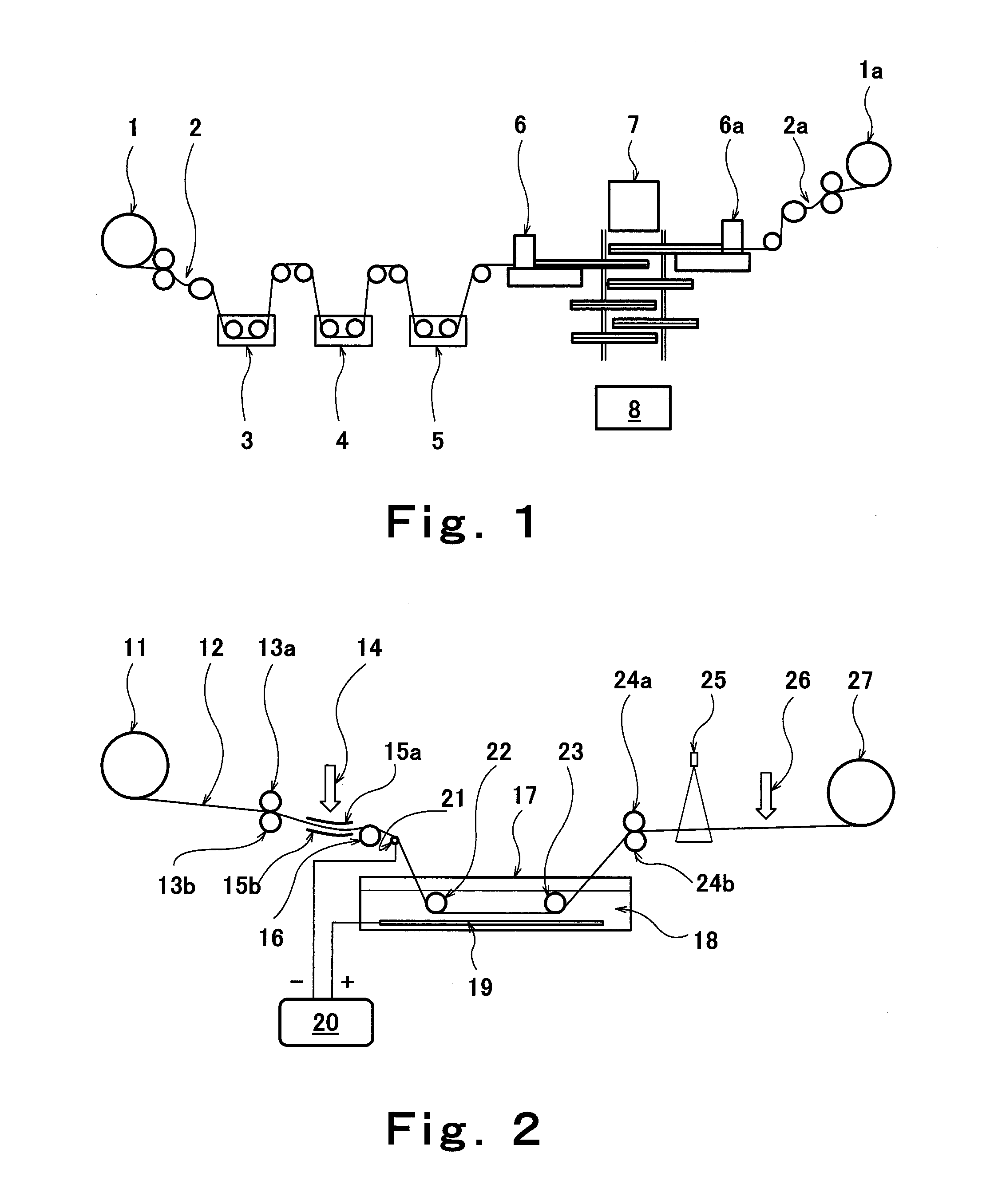
[0138]A stacked body of a fiber negative electrode for use in a lithium ion secondary battery and a separator was obtained by using the fiber electrode fabrication apparatus shown in FIG. 2.

[0139]In Example 4, the electrolytic bath 17 is filled with an aqueous solution for Li3PO4 plating, which is obtained by dissolving lithium nitrate (LiNO3) and sodium phosphate (NaH2PO4) at rates of 0.1 mol / L and 0.02 mol / L, respectively, in ion-exchanged water.

[0140]The DC power supply 20 was energized, and electrodeposition was performed for 10 minutes while the reel roller 27 was rotated at a speed of 5 cm / min to wind the PAN-based carbon fiber tow 12. The temperature of the bath in the electrolytic bath 17 was kept at 25° C. and an inter-electrode voltage was maintained at 7V. A fiber of the PAN-based carbon fiber tow 12, on which the electrodeposition had been performed, was observed with an optical microscope. It was confirmed that a Li3PO4...

example 1

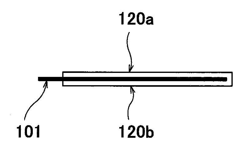
(6) Example 1 of Method of Fabricating Stacked Body of Fiber Positive Electrode and Separator

[0142]By using an apparatus shown in FIG. 5, a separator coating was formed on a fibrous nickel hydroxide positive electrode for use in an alkaline secondary battery, the positive electrode having been obtained in Example 2 of the fiber electrode fabrication method. In FIG. 5, the reference sign 101 denotes a sheet-like carbon fiber on which a nickel hydroxide coating is formed; the reference sign 102 denotes a spray configured to spray mist steam; the reference sign 103 denotes air blown from a fan (not shown); the reference sign 104 denotes a dripping device configured to drip slurry; the reference sign 105 denotes a scraper configured to scrape away the slurry that remains excessively on the carbon fiber; the reference sign 106 denotes warm air; the reference signs 108a and 108b denote pressing rollers configured to press slurry coatings 107a and 107b which have been applied to the upper ...


PUM


Abstract

The present invention provides a method of efficiently fabricating a large number of fiber electrodes at the same time from a large number of fibers while taking advantage of inherent characteristics of fiber electrodes.
A fiber electrode fabrication method according to the present invention includes: a step (2, 2a) of spreading a fiber tow; a step (3, 4, 5) of obtaining fiber positive electrodes or fiber negative electrodes by forming a positive electrode active material coating or a negative electrode active material coating on each of single fibers that are obtained by spreading the fiber tow; and a step (6, 6a) of forming a separator coating on the fiber positive electrodes or the fiber negative electrodes.

Description

TECHNICAL FIELD[0001]The present invention relates to fiber electrodes used in a battery or a capacitor, to a fiber battery formed by using the fiber electrodes, and to an apparatus for fabricating the fiber electrodes and the fiber battery. The fiber battery technology of the present invention is applicable to secondary batteries that use an aqueous solution as an electrolyte solution. Specifically, the fiber battery technology of the present invention is applicable to a nickel metal-hydride battery, nickel-cadmium battery, nickel-iron battery, nickel-zinc battery, or a lead battery. The fiber battery technology of the present invention is also applicable to secondary batteries of a nonaqueous electrolyte type, typically a lithium ion battery, and to air batteries or capacitors.BACKGROUND ART[0002]Conventional secondary batteries in which an aqueous solution is used as an electrolyte solution include a plate-shaped positive electrode, a separator, and a plate-shaped negative electr...

Claims


Application Information

Patent Timeline
IPC IPC(8): H01M4/02H01M2/10B32B38/10B32B37/12B05C11/00H01M2/30B05D5/12H01M4/13H01M4/139H01M10/058H01M50/209
CPCH01G11/26H01M4/75H01G11/50H01M2/0217H01M2/1061H01M4/0404H01M4/0409H01M4/139H01M4/1391H01M4/1397H01M4/66H01M10/0413Y02E60/122Y02E60/13H01M6/46H01M4/70H01G11/40Y02E60/10H01M50/103H01M50/209Y02P70/50H01M10/058H01M10/0525H01M2004/022H01M50/547H01M10/0468
Inventor TSUTSUMI, KAZUONISHIMURA, KAZUYATAKASAKI, TOMOAKINAKOJI, MASATERUSAKAISAITO, MAKOTOYAO, JINHANMUKAI, TAKASHI
Owner KAWASAKI HEAVY IND LTD
Why Eureka
Try Eureka