Biological laser plasma x-ray point source
a plasma x-ray point source and biological technology, applied in the direction of radioactive sources, electric discharge tubes, basic electric elements, etc., can solve the problems of unenvironment friendly use of high z-metal, difficult preparation of most of the systems used so far, etc., to optimize the emission characteristics of the source, improve the x-ray yield, and improve the effect of x-ray yield
- Summary
- Abstract
- Description
- Claims
- Application Information
AI Technical Summary
Benefits of technology
Problems solved by technology
Method used
Image
Examples
example 1
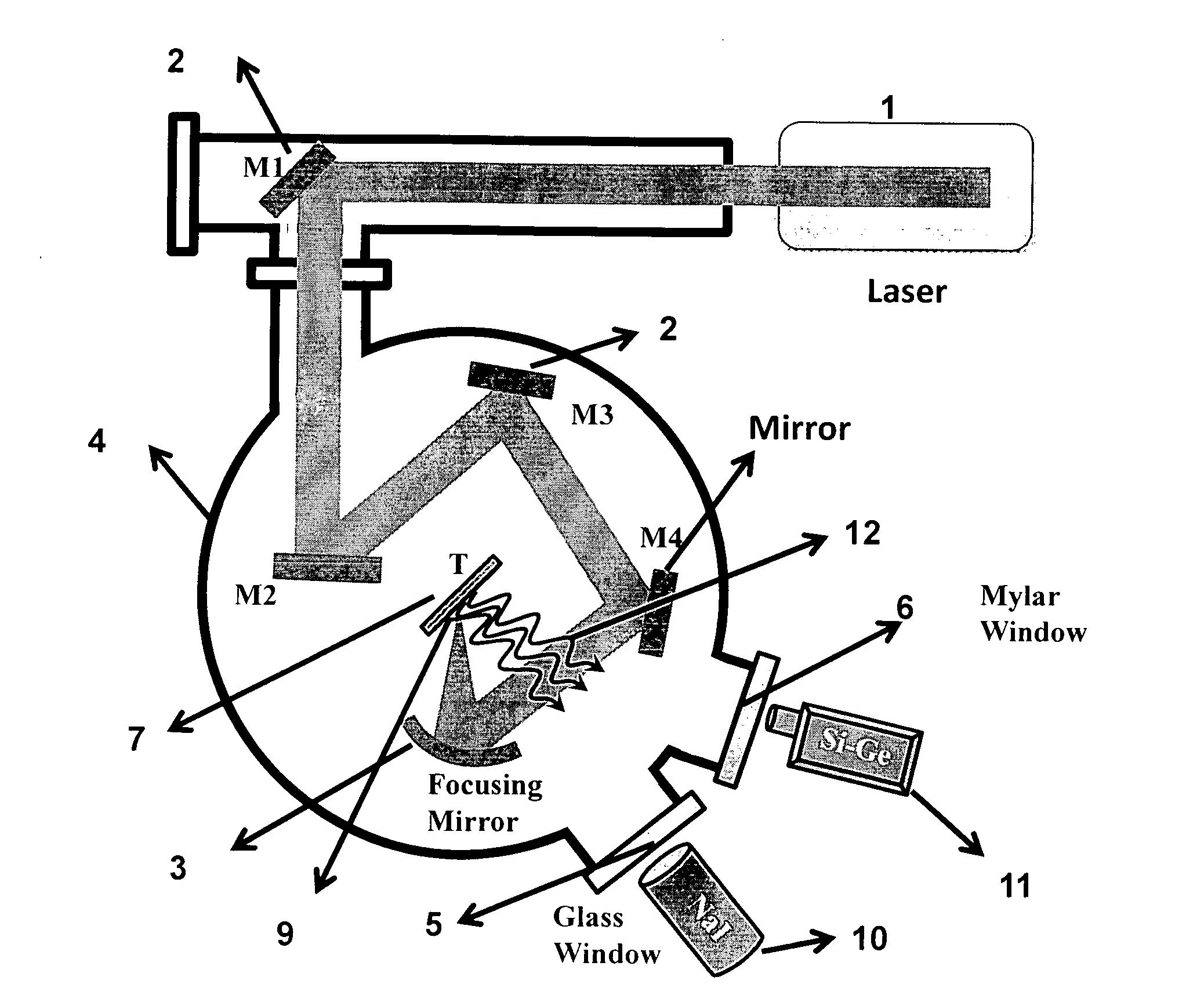
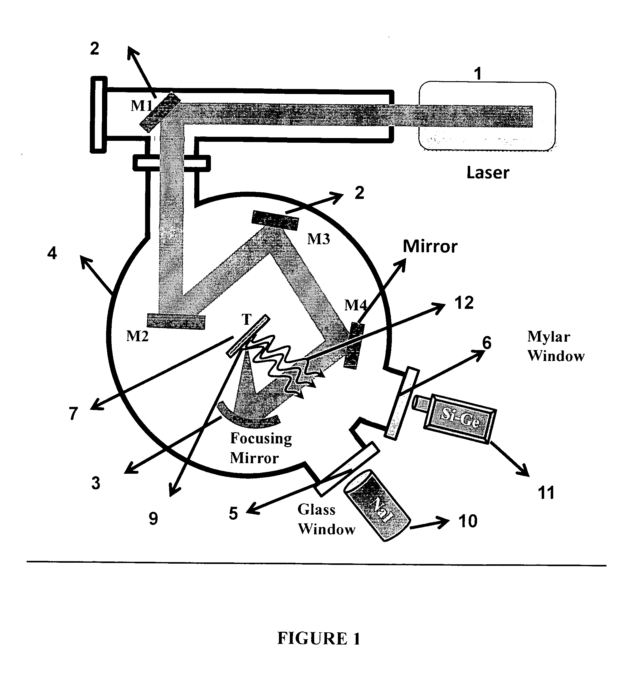
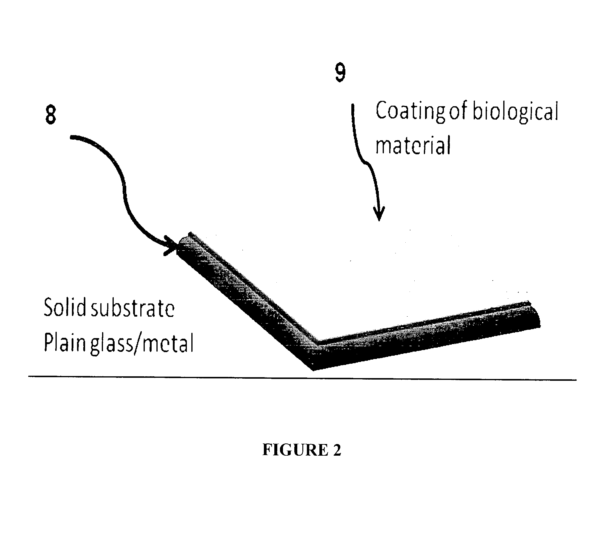
[0030]Bacterial suspension in formaldehyde and gluteraldehyde solutions was spread on a solid target and exposed to 250 mJ of 280-300 nm UV to attenuate and fix the cells on to the surface. The target preparation technique used is not unique. A preferred process used was to first paint the target with 1 mg / ml poly-L-lysine solution and then air-dry it for a few minutes. The poly-L-lysine coating creates charged surface on the substrate and thus helps to form uniform coating of the bacterial cells that stick well onto the surface. The cell-suspension, live or fixed, are spread over the charged solid surface and then air dried in a laminar flow hood followed by UV irradiation in a suitable chamber with appropriate dose. Many techniques can be used to spread the bacterial cells and any method, which would produce a uniform layer, would work for the target preparation. The coated target slabs are then left to dry in a desiccator.
example 2
[0031]The height profiles are shown to provide an idea of the uniformity of the coating on the target plates. Height measurements were done using Ambios Profilometer (Model X1-100). This justifies the practice of averaging the data collected from 10000 different positions on each of the coated target. FIG. 3 shows the height profile of the quoting obtained by the smearing method. Average sizes of E. coli cells are: width 700±88 nm and length 1880±432 nm. So the height profile is expected to vary from about 600 nm to 2200 nm if there is a monolayer of bacterial spread. FIG. 3 show that our spreading method generates coating well within these expectations and at most there are 2-3 cell layers of bacteria at certain points.
example 3
[0032]Femtosecond pulses were focused in the intensity range of 1014-1016 Wcm−2 on the coated target, which was obtained by the method explained in Example 1, and the X-rays emitted from the laser produced plasmas were measured under identical conditions, both from the solid target with the bacterial coating and without it. This gave the relative yields of the enhancements in the X-ray emissions due to the bacterial coating as compared to the bare surface. FIG. 4 shows the energy resolved X-ray spectrum measured with a NaI (Ti) detector. The X-rays are measured over a few thousand laser shots for both plain glass substrate and the bacterial coated surface. The data indicated in ‘A’ refers to the X-ray emission measurements from the laser irradiation of the bacterial coating. The data indicated in ‘C’ refers to the X-ray emission from plain glass substrate under otherwise identical conditions. The data presented in ‘C’ has been multiplied 5 times. The measured counts are normalized o...
PUM
 Abstract
Description
Claims
Application Information
 - R&D
- Intellectual Property
- Life Sciences
- Materials
- Tech Scout
- Unparalleled Data Quality
- Higher Quality Content
- 60% Fewer Hallucinations
Browse by: Latest US Patents, China's latest patents, Technical Efficacy Thesaurus, Application Domain, Technology Topic, Popular Technical Reports.
© 2025 PatSnap. All rights reserved.Legal|Privacy policy|Modern Slavery Act Transparency Statement|Sitemap|About US| Contact US: help@patsnap.com


