Microfluidic Cytochemical Staining System

a microfluidic cytochemical and staining technology, applied in the field of microfluidic tissue analysis, can solve the problems of increasing patient stress, increasing diagnosis time, and restricting the number of stains that can be used in diagnosis, so as to facilitate multiplexed staining of biological samples, enhance the effect of macro-fluidic systems, and improve the accuracy of disease diagnosis

Active Publication Date: 2012-09-13
COLORADO STATE UNIVERSITY
View PDF5 Cites 17 Cited by
  • Summary
  • Abstract
  • Description
  • Claims
  • Application Information

AI Technical Summary

Benefits of technology

[0004]The present invention provides devices and associated methods to facilitate multiplexed staining of a biological sample on a slide or other planar surface. The use of multiplexed staining on a single slide allows for more accurate disease diagnosis while also conserving sample. A PDMS based cytology overlay was created that is capable of coupling on-chip morphological, cytochemical, and immunological staining. Morphological and cytochemical staining of blood smears, along with immunostaining of lymph node imprints, was carried out to demonstrate the application of this microfluidic cytology chip (μCC) device. One important advantage of the μCC device is that the architecture creates an environment “continuous flow” of reagent. Recent efforts towards enhanced efficacy in macro-fluidic systems attempt to blow or vibrate puddles of reagent around on the surface of a slide. As an alternative, it is proposed to create a flow of reagent over the surface. This flow provides an inherent advantage in that the μCC device provides an environment where reagent is continuously moved over the sample. In essence, the system is able to put bio-targets into contact with a continuous flow of the markers that are seeking to find them on a microscopic level. In the hands of the clinician the technology should allow for a more comprehensive diagnosis, leading to a better life science outcome.

Problems solved by technology

In contrast, the number of submitted slides for commonly obtained cytology samples, such as fine needle aspirates, tissue imprints, and fluid preparations are often limited, restricting the number of stains that can be used in diagnosis.
If an additional cytochemical or immunocytological staining is deemed necessary, re-sampling is often required, resulting in increased costs, time to diagnosis, and additionally, increased patient stress.

Method used


Image

  • Microfluidic Cytochemical Staining System
  • Microfluidic Cytochemical Staining System
  • Microfluidic Cytochemical Staining System

Examples


example 1

Materials and Methods

[0074]The following chemicals, biologicals, and supplies were used in the manufacturing and testing of this device: SU-8 3025 photoresist (Micro-Chem. Corp., Newton, Mass.), PDMS (Dow Corning, San Diego, Calif.), Sygard 184 elastomer curing agent (Dow Corning), methanol (Fisher, Pittsburg, Pa.), triton X-100 (Fisher), acetone (Mallinckrodt Chemicals, Phillipsburg, N.J.), isopropyl alcohol (Mallinckrodt), hydrogen peroxide (Mallinckrodt), SuperBlock T20 (PBS) Blocking Buffer (Thermo Scientific, Rockford, Ill.), propylene glycol monomethyl ether acetate (Sigma-Aldrich, St. Louis, Mo.), 4-in. silicon wafers (Silicon Inc., Boise, Id.), IMEB Diff Stain Kit (San Marcos, Calif.), Histochemical Reaction Set—Ferric Iron (EMD Chemicals, Inc., Gibbstown, N.J.), 1×3 inch pre-cleaned glass micro slides (Corning Inc., Corning, N.Y.), 1×3 inch pre-cleaned glass microscope slides (Fisher), 10 mL syringes (Beckton Dickinson, Franklin Lakes, N.J.), 21 ga. 1 inch needles (Beckton ...

example 2

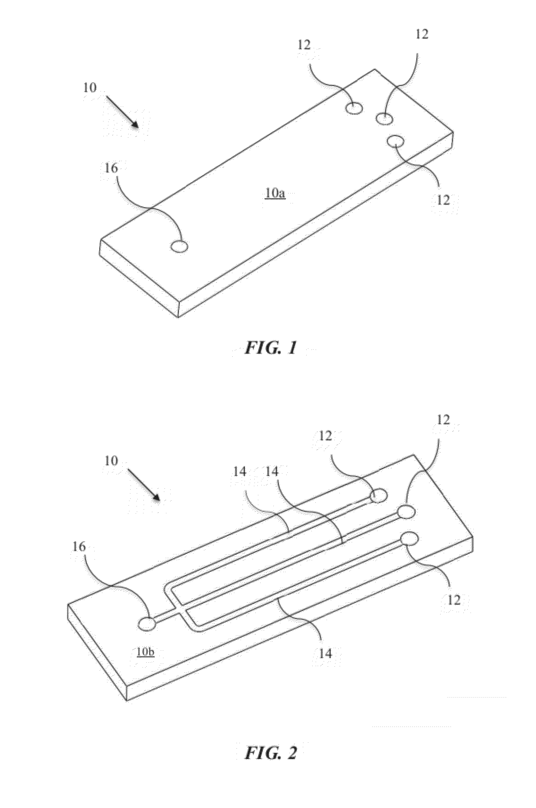
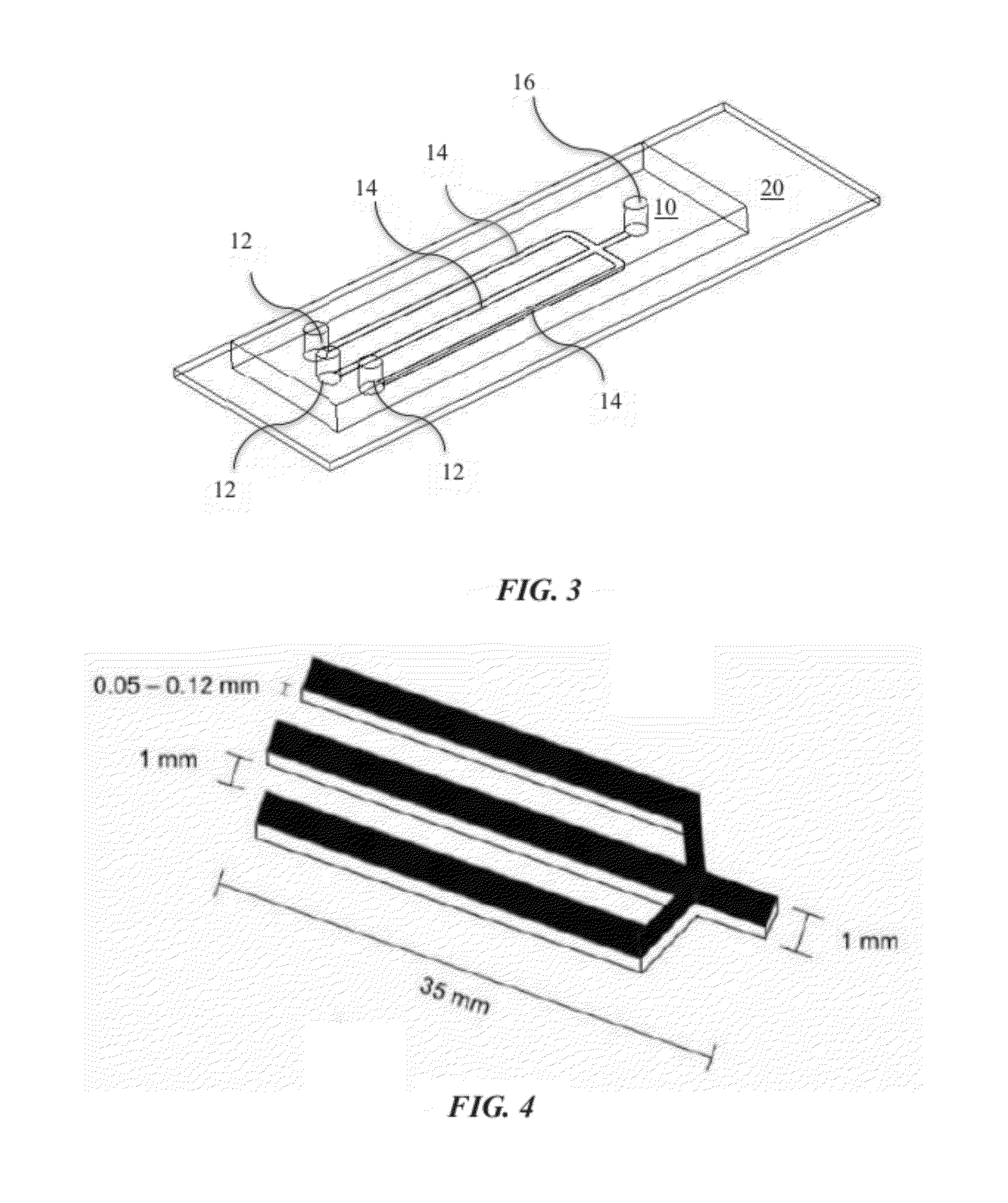
μCC Device Fabrication

[0077]Polydimethylsiloxane (PDMS) μCC overlays were fabricated using SU-8 soft lithography methods published previously. [McDonald, J. C., et al., Electrophoresis, 2000, 21, 27-40; J. C. McDonald and G. M. Whitesides, Acc Chem Res, 2002, 35, 491-499; S. K. Sia and G. M. Whitesides, Electrophoresis, 2003, 24, 3563-3576; Liu, Y., et al., Anal Chem, 2000, 72, 5939-5944; Liu, Y., et al., Anal Chem, 2004, 76, 1513-1517; Liu, Y., et al., Analyst, 2001, 126, 1248-1251]

[0078]Briefly, PDMS molds were prepared on silicon wafers (Silicon Inc.) that were spin coated with SU-8 3025 photoresist (Microchem). The coated silicon wafer was covered with a photomask and exposed to UV light. The silicon wafer was then developed in propylene glycol monomethyl ether acetate (Sigma-Aldrich) leaving behind only [Banham, A. H., et al., Clin Cancer Res, 2005, 11, 1065-1072; Hoeller, S., et al., Histopathology, 2010, 57, 73-80] the desired features on the silicon wafer. Molds were prepare...

example 3

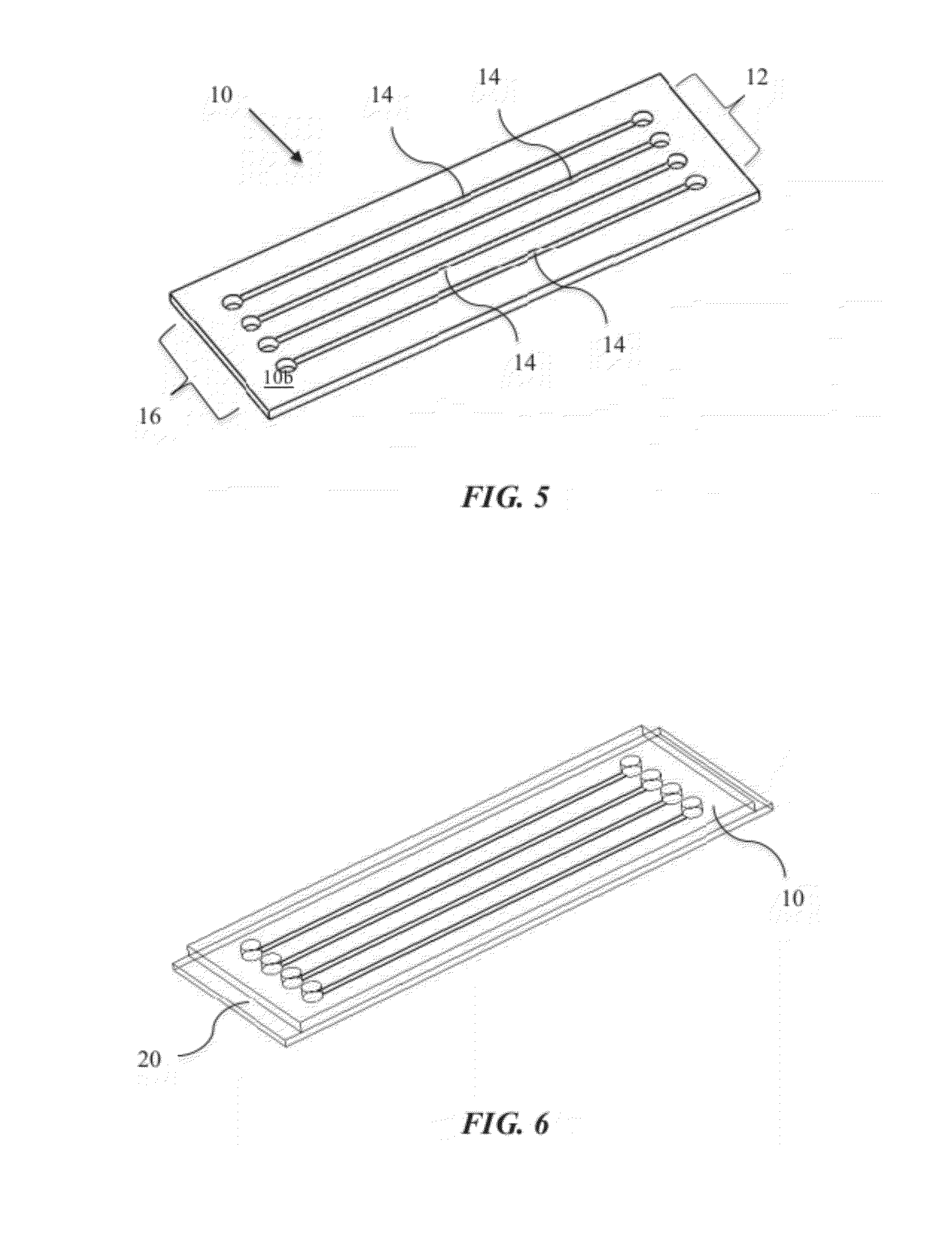
Immunocytochemistry Techniques Using the μCC Device

[0080]Immunocytochemistry (ICC) was carried out on slides based on techniques drawn from previously published methods. [Polak, J. M., and S. Van Noorden, Introduction to immunocytochemistry, BIOS Scientific Publishers, Oxford, 2003; Valli, V., et al., Vet Clin Pathol, 2009, 38, 261-269; Pettigrew, N. M., Arch Pathol Lab Med, 1989, 113, 641-644; Ponce, F., et al., J Vet Diagn Invest, 2003, 15, 330-337] All procedures detailed below were carried out at room temperature.

[0081]In brief, after fixation slides were air dried for at least one hour. After drying, slides were then treated with 0.1% Triton X100 (PBS) (Fisher) for 10 minutes. Slides were rinsed with PBS, then blocked (SuperBlock T20, Thermo Scientific) for 30 minutes. After blotting off of the blocking medium, slides were air dried for 30 minutes before mounting the respective μCC. Once mounted, fluid flow was established by injecting 10 μL PBS into each channel and subsequent...


PUM


Abstract

The present invention provides devices and associated methods to facilitate multiplexed staining on a slide. The use of multiplexed staining on a single slide allows for more accurate disease diagnosis while also conserving sample. A PDMS based cytology overlay was created that is capable of coupling on-chip morphological, cytochemical, and immunological staining. Morphological and cytochemical staining of blood smears, along with immunostaining of lymph node imprints, was carried out to demonstrate the application of this microfluidic cytology chip (μCC) device.

Description

CROSS REFERENCE TO RELATED APPLICATIONS[0001]This application claims priority to currently pending U.S. Provisional Patent Application 61 / 450,416, entitled, “Microfluidic Cytochemical Staining System”, filed Mar. 8, 2011, the contents of which are herein incorporated by reference.FIELD OF INVENTION[0002]This invention relates to microscopic tissue analysis. More specifically, this invention relates to devices for multiplexed staining on a slide or other planar surface.BACKGROUND OF THE INVENTION[0003]Microscopic tissue analysis plays an extremely important role in the diagnosis of many diseases. With most incisional and excisional biopsy samples, tissues are fixed and embedded in paraffin blocks, allowing for the re-cutting of as many slides as necessary to ensure an accurate diagnosis. In contrast, the number of submitted slides for commonly obtained cytology samples, such as fine needle aspirates, tissue imprints, and fluid preparations are often limited, restricting the number of...

Claims


Application Information

Patent Timeline
Patent Type & Authority Applications(United States)
IPC IPC(8): B01L3/00
CPCB01L3/5027B01L2300/0816G01N1/312B01L2300/0864B01L2300/0822B01L3/502715
Inventor HENRY, CHARLESFEIRER, MATTHEWMENSACK, MEGHAN
Owner COLORADO STATE UNIVERSITY
Why Eureka
Try Eureka