Pressure measuring system, pressure measuring sensor assembly and a method of measuring a pressure

a pressure measurement and sensor technology, applied in the field of pressure measuring system, can solve the problems of sensor contamination, insufficient protection from contamination, and serious threat to reliable and accurate measurement and patient safety, and achieve the effect of removing the influence of pressure on the vessel adapter

Inactive Publication Date: 2012-09-13
SWISSTOM
View PDF13 Cites 13 Cited by
  • Summary
  • Abstract
  • Description
  • Claims
  • Application Information

AI Technical Summary

Benefits of technology

[0083]step b serves to eliminate pressure influence from the vessel adapter by mechanically positioning the floppy membrane to a deflated start position.
[0084]Once steps a and bare executed, the baseline of all pressure sensors can be reliably measured and compensated in later measurements.

Problems solved by technology

However, water vapor condensation, mucus, blood, and possibly other body fluids as well as infectious agents may be present in the airway tubing and present a serious threat to reliable and accurate measurement and patient safety.
However, protection from contamination is not complete and water vapour can easily move into the sensing tubes by means of diffusion.
While the state-of-the-art is working well, it has a number of disadvantages: the sensing tubes are prone to kinking and disconnection, the purge flows interrupt the measurement process and introduce measurement errors and thus need to be checked regularly, disconnection of sensing tubes is difficult to monitor by the ventilator or the anesthesia machine and is a safety concern, and contamination of the sensors is not completely avoided if the purge flows stop—for example if the ventilator or the anesthesia machine is stored with the tubing still attached.
Finally, the response time of the ventilator or the anesthesia machine is degraded by long sensing tubes and this limits the rapid response to breathing efforts of the patient, for example in Automatic Tube Compensation.
Such limitation may be so strong that spontaneous breathing becomes impossible if the patient is very weak, and this in turn will lead to longer time on the ventilator with associated risks for infection, complications and death.
Thus contaminated patient air still may reach transducer parts and therefore diminish its reusability.

Method used


Image

  • Pressure measuring system, pressure measuring sensor assembly and a method of measuring a pressure
  • Pressure measuring system, pressure measuring sensor assembly and a method of measuring a pressure
  • Pressure measuring system, pressure measuring sensor assembly and a method of measuring a pressure

Examples


first embodiment

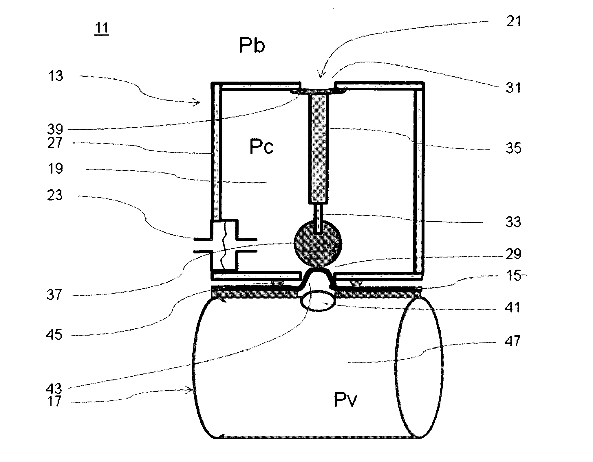
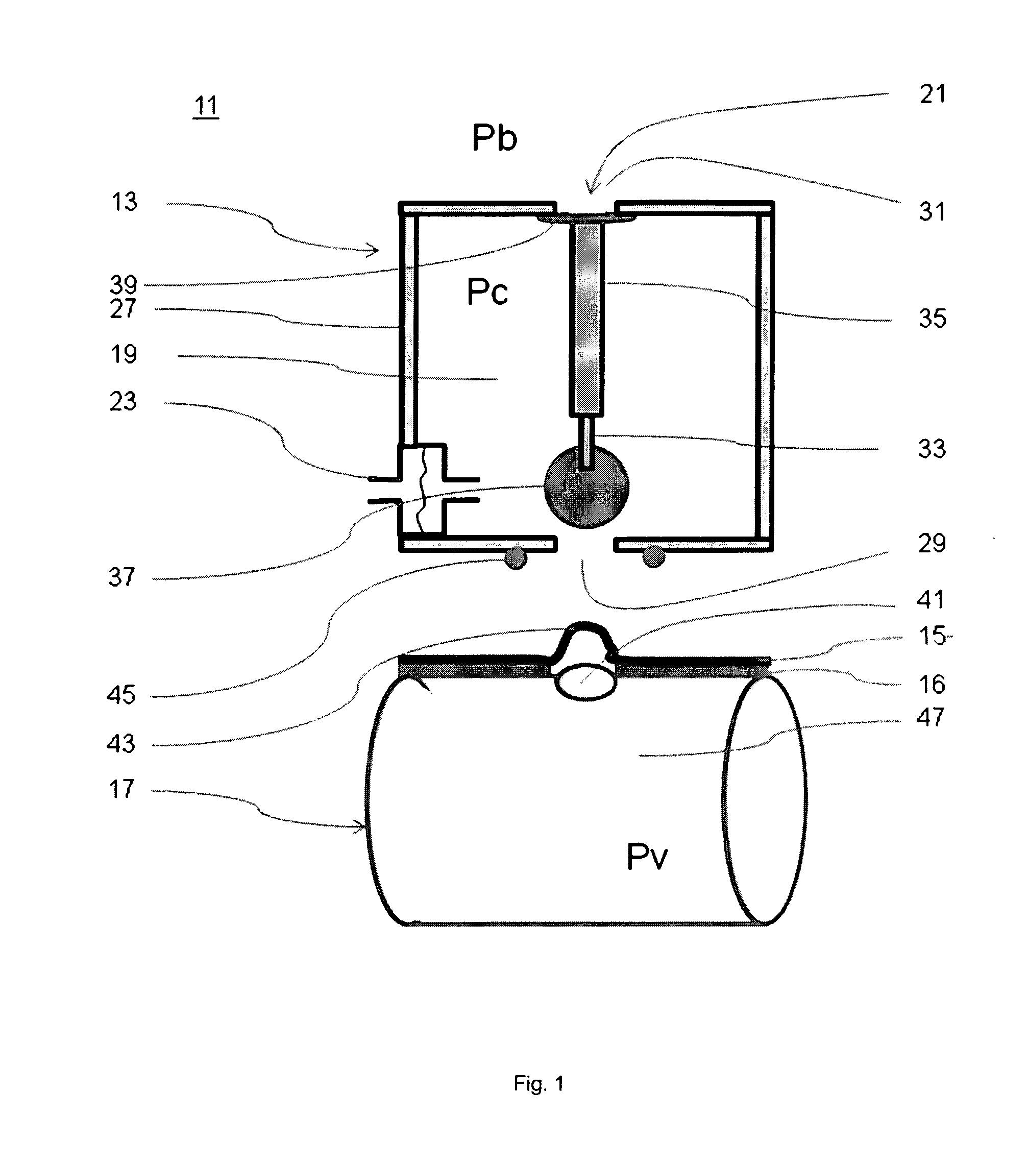
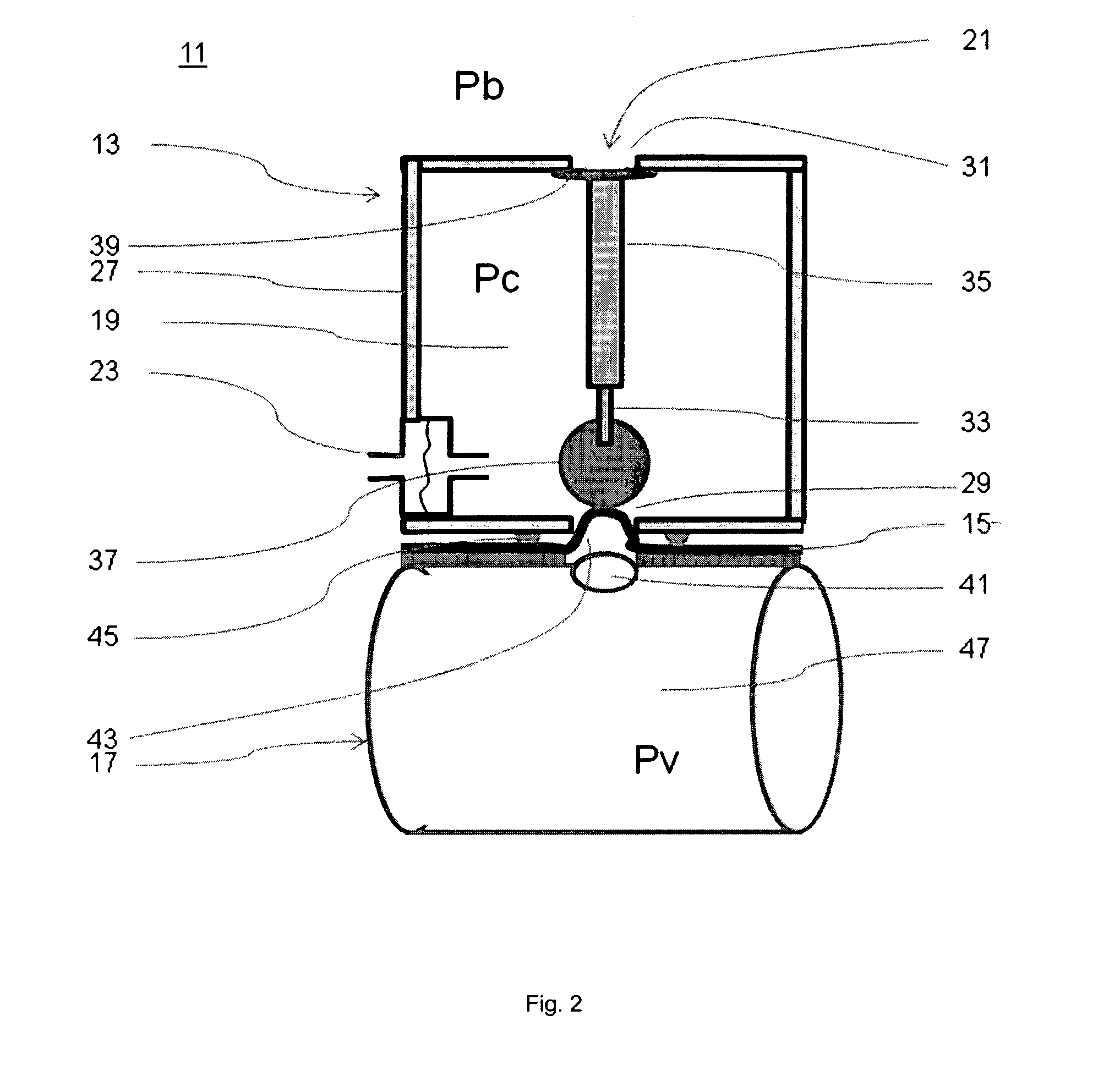
[0103]FIGS. 1 to 5 show a pressure measuring system 11 comprising a sensor assembly 13 and a membrane 15 covered vessel adapter 17. In FIG. 1 sensor assembly 13 and membrane 15 covered vessel adapter 17 are presented in a disconnected arrangement. The sensor assembly 13 comprises a compartment 19 with an actuator 21 and a pressure sensor 23. The pressure sensor 23 is arranged on or integrated in a side wall 27 of the compartment. In this way the sensor is able to measure the pressure in the compartment 19 relative to the given ambient pressure outside the compartment. The compartment 19 comprises two openings, a measurement port 29 and a release port 31. The actuator 21 consists of a pusher 33 and a stem 35. The pusher 33 is equipped with a pusher head 37. The stem 35 is equipped with a valve means 39. Pusher 33 and stem 35 of the actuator 21 are movably connected to each other. Pusher 33 and stem 35, thus the entire actuator 21, are axially movably mounted. Hereby pusher 33 and ste...

second embodiment

[0157]The present invention, in particular the second embodiment, can be used as a stand-alone pneumotachograph for lung function testing in a pulmonary function lab or as a screening tool in a general physicians practice. It can also be used to measure pressure and flow in respiratory assist devices, intensive care ventilators, home care ventilators, and emergency ventilators. A further use is in anesthesia machines. Yet another use is in vital signs monitors to monitor flow, pressures, inspired volumes and expired volumes of air, and other respiratory parameters. Yet another use is in ventilatory support devices for closed-loop control of respiratory gas delivery, pressure delivery, or breath delivery in general. Such use includes but is not limited to intensive care or emergency ventilators, home care ventilators, and anesthesia machines.


PUM


Abstract

A pressure measuring System (11, 111, 211) is described comprising a sensor assembly (13, 113, 213) and a vessel adapter (17, 217), with the sensor assembly defining a compartment (19, 119, 219, 220), comprising a measurement port (29, 129, 229, 230), an actuator (21, 121, 221, 222) for enabling and disabling pressure transmission across the measurement port, and at least one pressure sensor (23, 123, 223, 224, 225) for measuring a pressure in the compartment relative to a reference pressure, and the vessel adapter defining a fluid chamber (47, 247, 248), said chamber being in pressure connection with the compartment by means of said measurement port, and characterized in that in-between the compartment and the fluid chamber at least one membrane (15, 215) is located which separates the medium in the compartment from the medium in the fluid chamber. The pressure measuring System is used to measure the pressure of a medium in a vessel adapter relative to a reference pressure. In a further embodiment the pressure measuring System is adapted to measure the differential pressure of a medium flowing through a vessel adapter with a flow restrictor.

Description

CROSS-REFERENCE TO RELATED APPLICATIONS[0001]This application claims priority to Swiss Patent Application Serial No. 1722109 filed on Nov. 9, 2009 and International Application Number PCT / CH2010 / 000269, filed on Oct. 26, 2010, the entirety of each of which is incorporated by this reference.BACKGROUND[0002]1. Technical Field[0003]This invention relates to a pressure measuring system, a pressure measuring sensor assembly, a vessel adapter, a ventilator system, a blood pressure measuring system and a method for measuring pressure.[0004]2. Background[0005]Flow and pressure of air in the lungs are important data for intensive care ventilators and anesthesia machines. In fact, monitoring of these parameters is mandated by the pertinent standards today. There is consent among the experts that measurement directly at the airway opening is the best way to measure. However, water vapor condensation, mucus, blood, and possibly other body fluids as well as infectious agents may be present in th...

Claims


Application Information

Patent Timeline
Patent Type & Authority Applications(United States)
IPC IPC(8): A61B5/03A61B5/021
CPCA61B5/0876G01L7/00G01F1/383A61B2562/0247
Inventor BRUNNER, JOSEF X.BOHM, STEPHAN H.
Owner SWISSTOM
Why Eureka
Try Eureka