
Method and apparatus for thermal control within a machining process

a technology of thermal control and machining process, which is applied in the direction of metal-working machine components, maintenance and safety accessories, metal-working apparatus, etc., can solve the problems of flooded applications, damage which requires repair, realignment and downtime, and is quite difficult to control during micro-machining or high-precision applications

Inactive Publication Date: 2012-09-20
COOL CLEAN TECH
View PDF10 Cites 18 Cited by
  • Summary
  • Abstract
  • Description
  • Claims
  • Application Information

AI Technical Summary

Benefits of technology

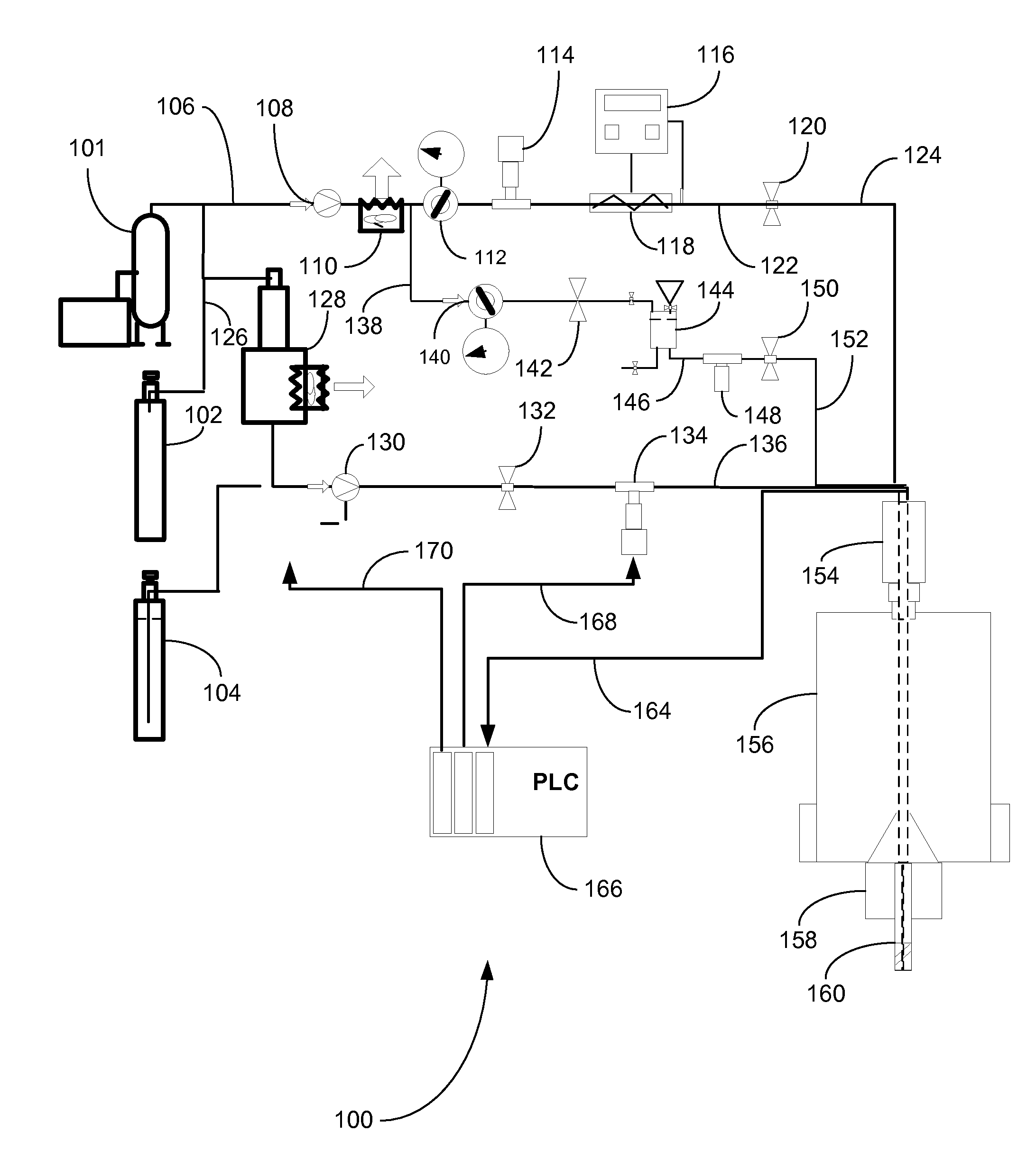
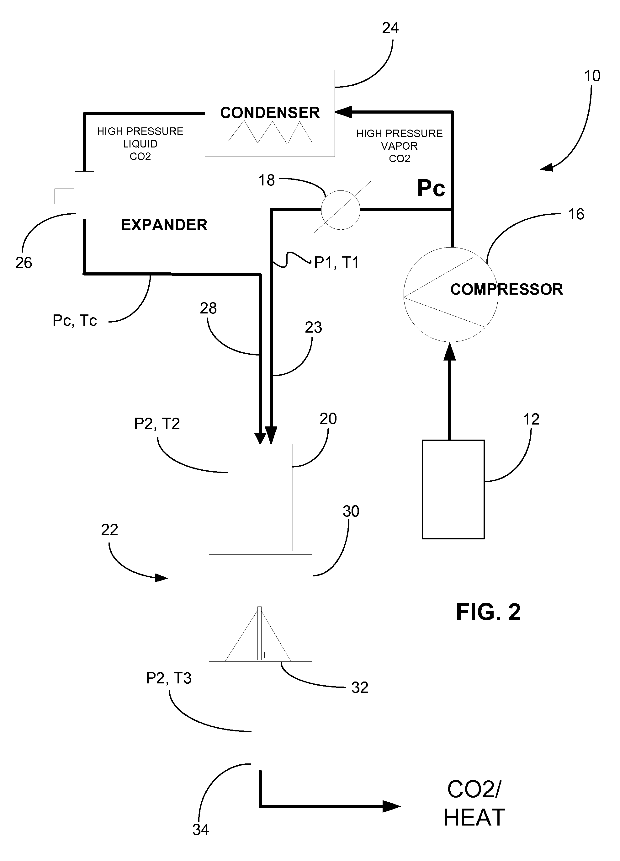
[0008]The present invention provides a method of mixing within a rotary union of a computer numerical control (CNC) machine a constant pressure gas with a relatively higher-pressure, lower-temperature dense fluid to produce a dense isobaric fluid deliverable through a rotating tool without gelling or solidifying therein. The constant pressure gas may include carbon dioxide, nitrogen, air or mixtures thereof. The dense fluid preferably includes liquid carbon dioxide at or above its triple point of −58° F. (−50° C.) and 74 psi (5 atm). The liquid carbon dioxide and isobaric gas are independently fed to the rotary union. When mixed, a pressurized flowing carbon dioxide machining fluid composition is formed exhibiting a temperature between about 20° F. (−7° C.) and 70° F. (21° C.) at pressures between 75 psi (5 atm) and 1,000 psi (68 atm). Optionally, lubricants may be added to the mixture. The mixture is deliverable through the rotating spindle without gelling or solidifying therein. Upon exiting ports positioned in or proximate the tool, the machining fluid instantly condenses under reduced ambient pressure conditions, forming a mixture of solid carbon dioxide particles and gas capable of removing heat from the tool / cutting surface interface as well as providing lubricating properties thereto.

Problems solved by technology

Not only are such techniques messy during application and produce large waste streams which have to be recycled, but due to the ever increasing complexity of CNC machining and the number of moving parts, it has become quite difficult to position nozzles and feed lines to properly apply the flooded coolant or lubricant.
Often times, the moving parts of the CNC machine contact the nozzles or feed lines, causing damage which require repairs, realignment and downtime.
Also, flooded applications are quite difficult to control during micro-machining or high-precision applications.
However, with regard to rotating tools having a spindle attached to a rotary coupling, it has been difficult to employ cryogenic fluids.
Because the cryogenic fluid enters the tool through the rotary coupling, the spindle or rotary coupling experiences a great difference in temperature relative to the ambient air, which in turn can lead to condensation or frosting on external surfaces, or clogging of nozzles.
This problem is exacerbated if an oil or other lubricant is mixed with the cryogenic fluid, which must be done at or before the rotary coupling, and the oil or lubricant tends to become quite viscous or freezes entirely before exiting the tool.
Without the use of cryogens, prior art processes tend to be time consuming and quickly wear down cutting tools.
This not only adds to replacement costs, but more importantly, diminishes overall quality of the machining process, especially where extremely high precision is needed.
Moreover, conventional cooling fluids, such as water-oil emulsions, are first refrigerated ex-situ and then transported internally to the cutting zone, cooling everything along its path and introducing secondary waste, maintenance and cleaning issues.
Refrigerated air is typically not used in long through-system coolant networks because it is ineffective due to its low heat capacity.
Subsequently, system heat and rotary seal compatibility issues can become a significant constraint using this conventional approach.
More important, additive schemes become extremely limited due to the selective solubility of both liquid and supercritical carbon dioxide coolants.
Still moreover, conventional coolant approaches do not provide the productivity needed in today's highly competitive business climate.
Heat is the enemy of productivity in many processes and generally too much heat leads to quality control problems.

Method used


Image

  • Method and apparatus for thermal control within a machining process
  • Method and apparatus for thermal control within a machining process
  • Method and apparatus for thermal control within a machining process

Examples


example 1

[0027]Several tests were performed to determine the efficiency of the present invention. The tests were performed on a CNC milling machine. Test cuts were made with tool steel. Test cuts were performed to verify the CNC machine program was configured properly. Once the programming was verified, Control Runs were performed with 6AL4V Titanium. For this phase of testing, ten block of 6AL4V Titanium were available and were all used during the different test cuts.

Control Run

[0028]A first control run was done using flood techniques of the prior art. The below machining specifications for each cut have been optimized to provide a balance of productivity and tool life for this material and coolant / lubrication system. Five control test pieces were machined to verify repeatability.[0029]Tooling: Face mill; 2″ diameter; 4 inserts; approximately 0.118″ diameter coolant port for each insert.[0030]Insert: Ultra Tool 61012TA round insert for Ti[0031]Spindle Speed: 600 rpm[0032]Feed rate: 0.010″ / i...

example 2

[0037]A CNC coolant network in accordance with the present invention was used to test drilling of stacked titanium and carbon fiber reinforced plastic (CFRP) stack-ups. A 0.50 inch titanium plate having a thermocouple affixed thereto was drilled with a ported 0.25 inch diameter, uncoated carbide drill bit. The bit was run by a Cooper air-driven spindle and motor. The air-driven drilling system was adjusted to run at a drilling speed of approximately 600 rpm and at a drilling feed rate of approximately 1 inch per minute with no pecking

[0038]A machining coolant network of the present invention employing 100% carbon dioxide with a carbonated MQL lubricant additive of BOELUBE® was used as follows:[0039]Carbon dioxide over-pressure: 300 psi[0040]Liquid carbon dioxide injection feed: 3 pounds / hour[0041]Lubricant injection rate: 25 mls / hour

[0042]After a series of drilling tests to optimize the set-up, an actual drilling test series comprising 3 holes each was performed comparing the presen...


PUM

PropertyMeasurementUnit
temperatureaaaaaaaaaa

Abstract

Method and apparatus for mixing within a rotary union of a computer numerical control machine a constant pressure gas with a relatively higher-pressure, lower-temperature dense fluid to produce a dense isobaric fluid deliverable through a rotating tool without gelling or solidifying therein. The constant pressure gas may include carbon dioxide, nitrogen, air or mixtures thereof. The dense fluid preferably includes liquid carbon dioxide at or above its triple point. The liquid carbon dioxide and isobaric gas are independently fed to the rotary union. When mixed, a pressurized flowing carbon dioxide machining fluid composition is formed exhibiting a temperature between about 20° F. and 70° F. at pressures between 75 psi and 1,000 psi.

Description

CROSS-REFERENCE TO RELATED APPLICATION(S)[0001]This application claims the benefit of U.S. Provisional Patent Application No. 61 / 454,206 filed on 18 Mar. 2011, which is hereby incorporated herein by reference.BACKGROUND OF INVENTION[0002]The present invention relates to metalworking or machining processes, such as through the use of drills, lathes, grinders, milling and hard-turning apparatuses. More particularly, the present invention relates to the thermal control of a coolant or minimum quantity lubricant within the metalworking or machining process.[0003]The use of computer numerical control (CNC) machining tools within metalworking and machining processes has drastically increased over the past two decades, and shows ever increasing applications. CNC machines, with the assistance of computer aided drafting (CAD), can machine a block of metal into an infinite number of different shaped parts. One such CNC machine includes a setup wherein a block of metal is positionably suspende...

Claims


Application Information

Patent Timeline
Patent Type & Authority Applications(United States)
IPC IPC(8): B23Q11/12
CPCY10T409/303976B23Q11/1061
Inventor DIONNE, JASONSCHILLER, DANJACKSON, DAVID P.
Owner COOL CLEAN TECH
Learn More