Fuel injection control apparatus of internal combustion engine

a technology of control apparatus and internal combustion engine, which is applied in the direction of electrical control, process and machine control, etc., can solve the problems of further detriment to exhaust emissions, achieve the effects of reducing the negative workload of the compression process, reducing the temperature and pressure in the combustion field, and suppressing the amount of nox generation and smoke generation

Active Publication Date: 2012-10-04
TOYOTA JIDOSHA KK
View PDF3 Cites 19 Cited by
  • Summary
  • Abstract
  • Description
  • Claims
  • Application Information

AI Technical Summary

Benefits of technology

[0026]Additionally, the fuel injection (auxiliary injection) that causes a low-temperature oxidation reaction at the point of time when the compression gas temperature reaches 750K in the compression process is an early injection (for example, BTDC 40 to 25° CA) before the compression top dead center. This ensures a wide range of fuel injection, over a wide space, compared with a fuel injection made at a position closer to TDC (for example, at BTDC 25° CA or later), and realizes reductions in temperature and pressure in the combustion field. This makes the premixed combustion by the auxiliary injection slow, following a gradual temperature increase (in-cylinder gas temperature transition). This realizes combustions with suppressed amounts of NOx generation and smoke generation. Further, with the premixed combustion before the compression top dead center made slow, a loss (negative workload) in the compression process decreases.
[0027]Additionally, even when a change is made to the fuel composition (for example, when a fuel of a low cetane value is used), there is approximately no influence of the change of the fuel composition, since the combustion of the low-temperature oxidation reaction starts in a temperature controlled manner (see FIG. 6). Accordingly, the low-temperature oxidation reaction constantly and stably provides an ignition field for the high-temperature oxidation reaction. Thus, there is an additional advantage of little influence of a change of the fuel composition.
[0028]Next, the injection time of the auxiliary injection for the premixed combustion will be described.
[0030]The injection time of the auxiliary injection may be a time when the fuel injected at the auxiliary injection starts an oxidation reaction at the point of time when the in-cylinder gas temperature reaches 750K (which is the start temperature for the high-temperature oxidation reaction). Preferably, the injection time of the auxiliary injection may be a time when a spray of fuel injected at the auxiliary injection vaporizes entirely before the in-cylinder gas temperature reaches 750K.
[0031]Additionally, as described above, the fuel injection (auxiliary injection) that causes the low-temperature oxidation reaction at the time when the compression gas temperature reaches 750K is a BTDC early injection. As the injection time is advanced, a wider range of fuel injection, over a wide space, results. If, however, the injection time of the auxiliary injection is excessively advanced, unburned HCs (hydrocarbons) increase. In order to inhibit the increase, it is necessary to restrict the advance angle amount of the auxiliary injection using an advance angle guard value. The advance angle guard value may be determined by an experiment, a simulation, or the like in consideration of the amount of generation of unburned HCs.
[0033]With the present invention, the fuel injection by the auxiliary injection ends before the gas temperature inside the cylinder reaches the temperature at which the fuel starts the low-temperature oxidation reaction, in a fuel injection control apparatus of a compression self-igniting internal combustion engine that is configured to carry out the main injection causing a combustion mainly including a diffusion combustion and the auxiliary injection carried out prior to the main injection and causing a combustion mainly including the premixed combustion. This ensures a slow premixed combustion and ensures control of the premixed combustion in a temperature controlled manner in accordance with the transition of the in-cylinder gas temperature. This realizes systematic fuel injection control that facilitates the attempt to make appropriate injection modes.

Problems solved by technology

Additionally, if a combustion of a mixture in the combustion chamber results in an incomplete combustion, smoke occurs in the exhaust gas, to the further detriment of exhaust emissions.

Method used


Image

  • Fuel injection control apparatus of internal combustion engine
  • Fuel injection control apparatus of internal combustion engine
  • Fuel injection control apparatus of internal combustion engine

Examples


Embodiment Construction

[0045]Embodiments of the present invention will be described below by referring to the drawings.

[0046]In this embodiment, description will be given with regard to a case where the present invention is applied to a common rail in-cylinder direct injection multi-cylinder (for example, inline four-cylinder) diesel engine (compression self-igniting internal combustion engine) mounted in an automobile.

[0047]Engine Configuration

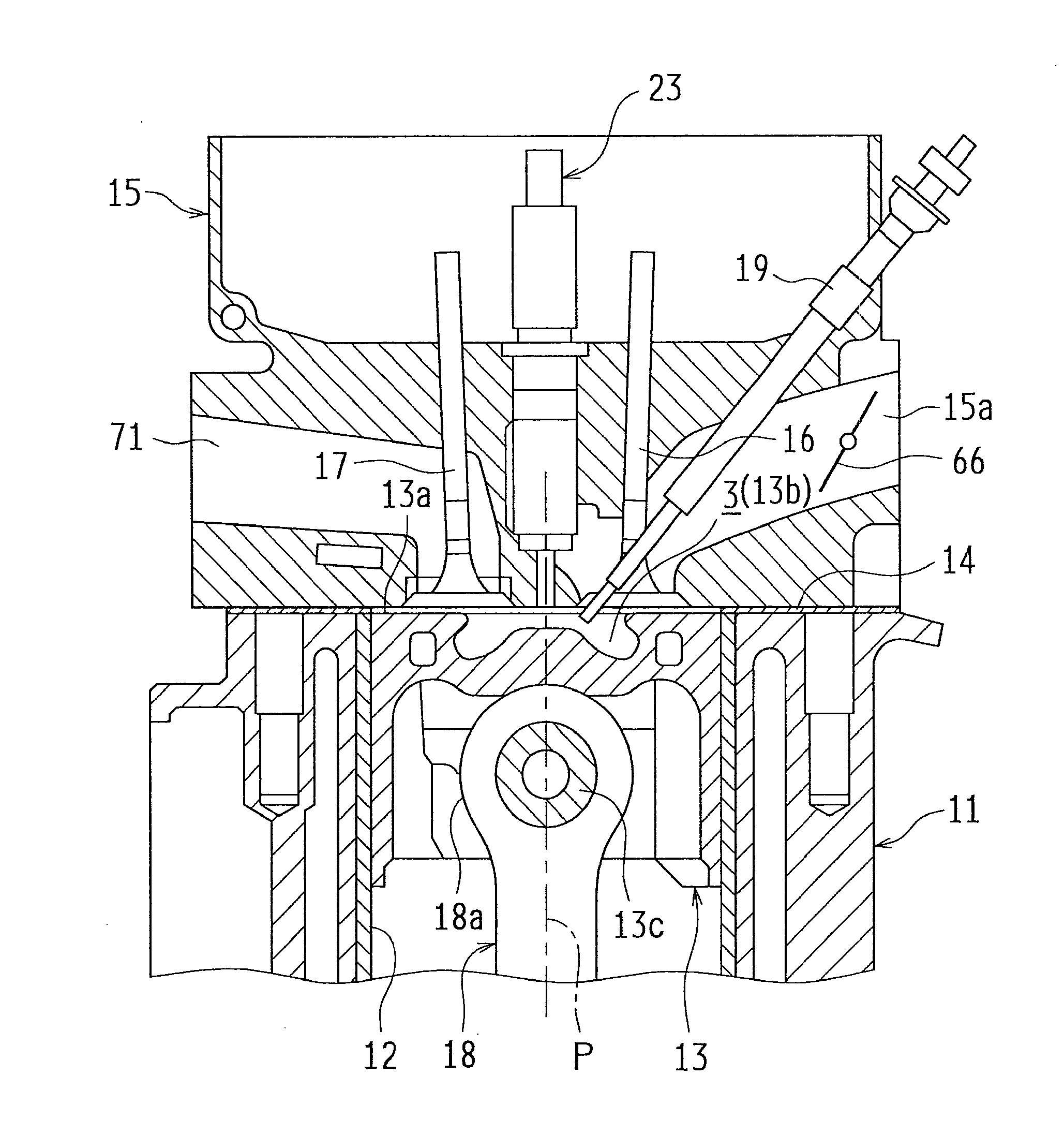
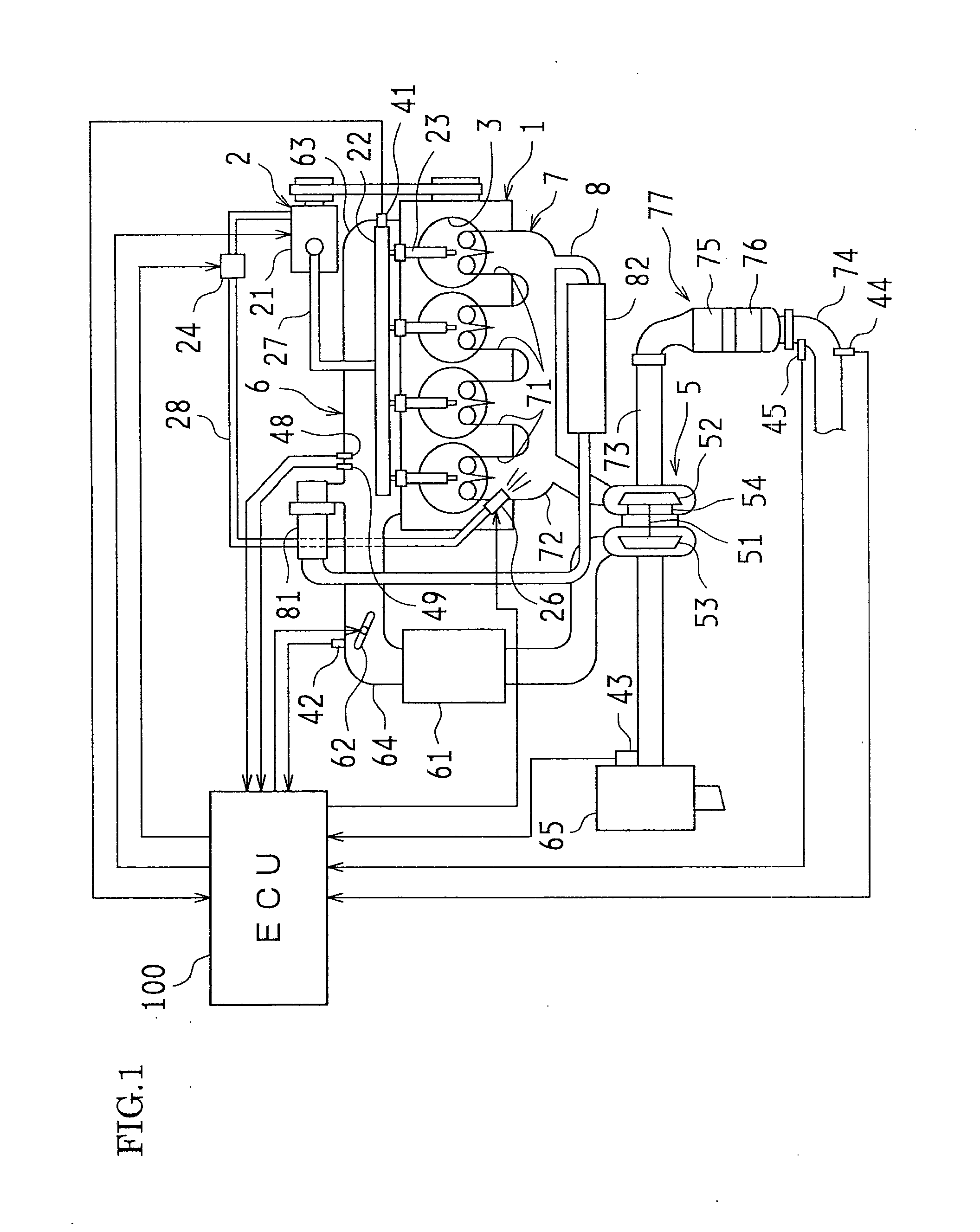
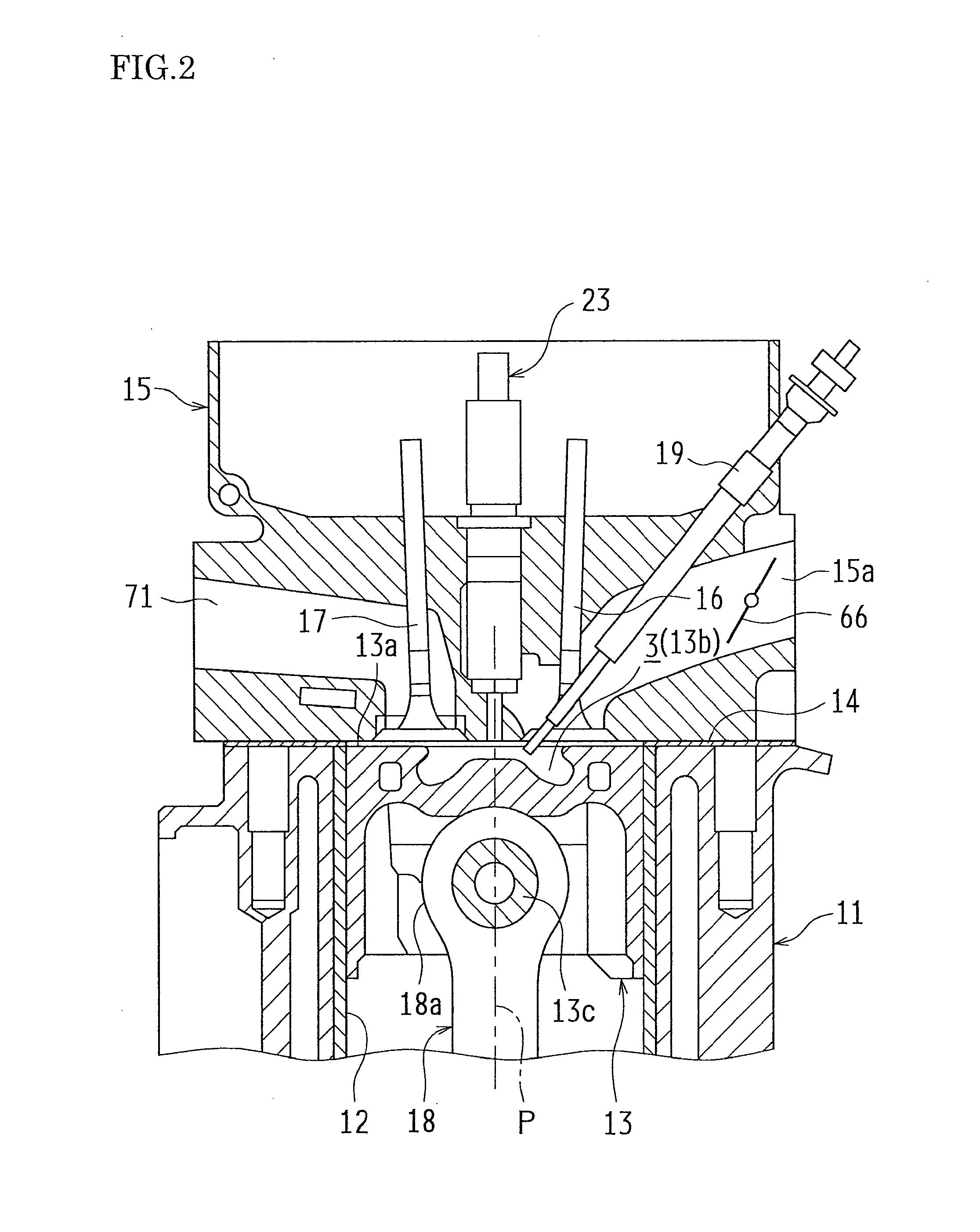
[0048]First, one example of a diesel engine (hereinafter referred to simply as an engine) to which the present invention is applied will be described. FIG. 1 is a schematic view of an engine 1 and its control system. FIG. 2 is a cross-sectional view of a combustion chamber 3 of the diesel engine and peripheral parts of the combustion chamber 3.

[0049]As shown in FIG. 1, the engine 1 of this example is configured as a diesel engine system including, as main units, a fuel supply system 2, combustion chambers 3, an intake system 6, and an exhaust system 7.

[0050]The fue...


PUM


Abstract

An auxiliary injection is carried out at an in-cylinder temperature at which a premixed combustion by the auxiliary injection is separatable into a low-temperature oxidation reaction and a high-temperature oxidation reaction, in a compression self-igniting internal combustion engine in which fuel injected into a cylinder from a fuel injection valve combusts in the cylinder, and that is configured to carry out an operation of fuel injection from the fuel injection valve. The operation of fuel injection includes at least a main injection and the auxiliary injection. The main injection causes a combustion mainly including a diffusion combustion in the cylinder. The auxiliary injection is carried out prior to the main injection and causes a combustion mainly including the premixed combustion in the cylinder. Specifically, an in-cylinder gas temperature (750K) is used as a reference, and the auxiliary injection is carried out before the in-cylinder gas temperature reaches 750K, so as to separate the low-temperature oxidation reaction and the high-temperature oxidation reaction from one another. This control makes the premixed combustion slow before a compression top dead center is reached, and ensures control of the premixed combustion in a temperature controlled manner in accordance with the transition of the in-cylinder gas temperature. This ensures unambiguous determination of the injection time of the auxiliary injection based on the in-cylinder temperature, and facilitates the attempt to simplify the fuel injection control.

Description

[0001]This is a 371 national phase application of PCT / JP2011 / 058086 filed 30 Mar. 2011, the content of which is incorporated herein by reference.FIELD OF THE INVENTION[0002]The present invention relates to a fuel injection control apparatus of an internal combustion engine typified by a diesel engine.BACKGROUND OF THE INVENTION[0003]In diesel engines used as automobile engines or the like, it is common practice to control the form of combustion, which takes place in a combustion chamber (in a cylinder), by adjusting the timing of fuel injection or the amount of fuel injection from a fuel injection valve (hereinafter also referred to as an injector) according to engine revolution, amount of accelerator operation, coolant temperature, intake air temperature, and the like.[0004]Diesel engine combustion, as disclosed in patent document 1 below, is mainly includes premixed combustion and diffusion combustion. When fuel injection starts from the injector into the combustion chamber, the f...

Claims


Application Information

Patent Timeline
Patent Type & Authority Applications(United States)
IPC IPC(8): F02D41/30
CPCF02D41/182F02D41/403F02D41/405Y02T10/44F02D2041/389F02D2200/0414F02D35/026F02D41/401Y02T10/40
Inventor NADA, MITSUHIRO
Owner TOYOTA JIDOSHA KK
Why Eureka
Try Eureka