System for measuring a time offset and method of measuring a time offset

Active Publication Date: 2012-11-22
SONARDYNE INT LTD
View PDF4 Cites 30 Cited by
  • Summary
  • Abstract
  • Description
  • Claims
  • Application Information

AI Technical Summary

Benefits of technology

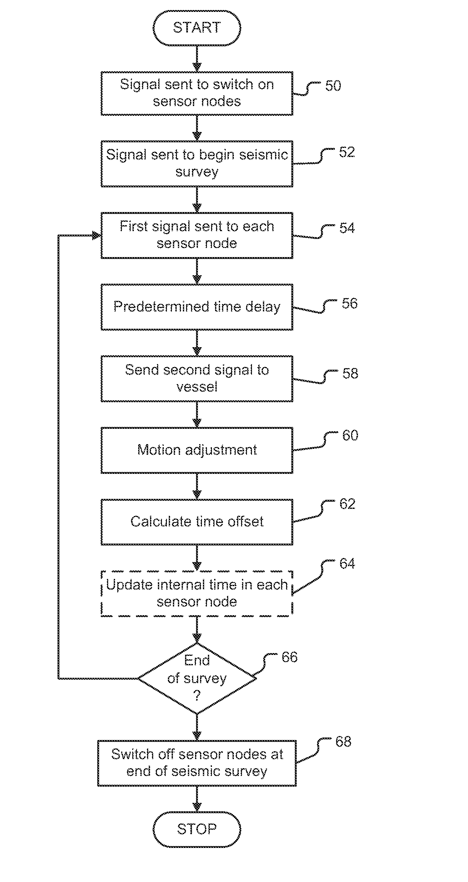
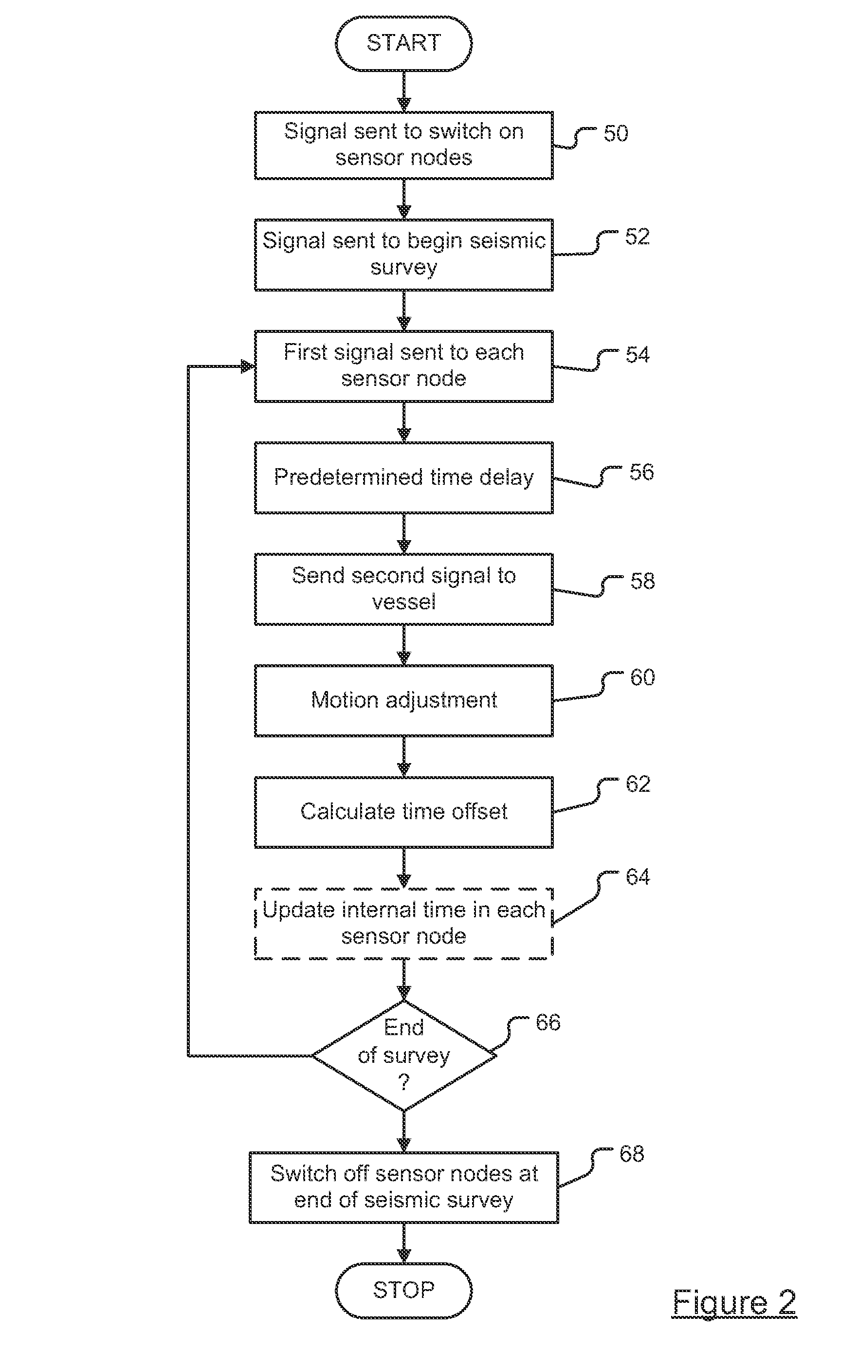
[0043]It is thus possible to provide a method and system having improved convenience and energy efficiency in relation to an arbitrarily sized array of sensor nodes. The sensor nodes are capable of supporting a standby power state, with no timing module running and no data recording. Prior to the start of the seismic survey, each sensor node can be powered up from the standby state via an acoustic control signal in order to be able to start recording data and then the time offset of each node relative to a reference time, such as UTC, can be measured remotely at a surface vessel.
[0044]The sensor nodes therefore operate in ‘recording mode’ only for the duration of the seismic survey. This may last only a few days. Therefore, overall battery endurance is significantly increased. By measuring time offsets immediately preceding and again after the survey, i.e. before/after the recording period of interest, this characterisation of time offsets can be used to maintain synchronisation accuracy during the recording period of interest in respect of seismic images to be generated. Also, any long term, for example 60 day, time drift has little effect on the seismic images that can be generated. The sensor nodes do not need to be synchronised to a reference time prior to and after each deployment. Consequently, reference time synchronisation and clock drift compensation of a sensor node whils

Problems solved by technology

If time synchronisation is not achieved to this accuracy, the resulting seismic images generated can be degraded and hence inaccurate.
In this respect, although measurements are made at the same time, the time noted by each sensor node as to when the measurements were made will not be aligned and so when the seismic images are reproduced by combination of the data collected by each individual sensor node, the misalignment of the measurement times between the sensor nodes will result in distortion of the image.
Such modules are susceptible to time drift, but can typically keep track of times at which samples are taken (“sample times”) to within an accuracy of a few tens of a millisecond over a 2 to 3 month deployment period before any time drift corrections need to be applied.
However, current nodal OBS systems suffer from a number of drawbacks that restrict the ability to perform seismic surveys accurately.
Firstly, the OCXO timing module draws significant power from the battery.
This power consumption accounts for a significant portion of the overall power demand of the sensor nodes and therefore typically restricts maximum deployment time to around 2 to 3 months

Method used


Image

  • System for measuring a time offset and method of measuring a time offset
  • System for measuring a time offset and method of measuring a time offset
  • System for measuring a time offset and method of measuring a time offset

Examples


Embodiment Construction

[0051]Throughout the following description identical reference numerals will be used to identify like parts.

[0052]Referring to FIG. 1, in a system for measuring time offsets an acoustic control system 10 is disposed in a surface vessel 12, which can be a ship or boat, the acoustic control system 10 being adapted to send and receive signals between an array of sensor nodes, generally indicated 14, disposed upon the seabed 16. The acoustic control system 10 comprises a processing resource 18, for example a processor, operably coupled to a communications hub 20, the communications hub 20 being coupled to an acoustic transceiver 22 for the purpose of sending and receiving acoustic signals to and from the sensor nodes 14. The acoustic transceiver 22 is attached to or integrally formed with the underside of the hull of the vessel 12 and so is immersed below the sea surface when in use. The acoustic transceiver 22 can be any suitable acoustic transceiver, for example a suitably adapted Fus...


PUM


Abstract

A system and method measures the time offsets of a plurality of acoustic sensor nodes relative to a reference time. The system includes an acoustic transceiver arranged to transmit a first signal to each acoustic sensor node and a processing resource arranged to record the transmission time of the first signal relative to the reference time. The acoustic sensor nodes receive the first signal and transmit a return second signal to the acoustic transceiver after a predetermined time delay, the second signal including the current acoustic sensor node internal time. The acoustic transceiver receives the second signal, and the processing resource records the time at which the second signal was received relative to the reference time and records also the combined time of flight of the first and second signal. From this data the time offset between the sensor node internal time and the reference time is calculated.

Description

[0001]This application claims priority to and benefit of co-pending U.K. Application No. 1108222.9, filed May 17, 2011, entitled “System for Measuring a Time Offset and Method of Measuring a Time Offset” to Sonardyne International, Ltd., which application is hereby incorporated in its entirety herein by reference.FIELD OF THE INVENTION[0002]This invention relates to a system for measuring a time offset of the type, for example, comprising a plurality of acoustic sensor nodes, such as subsea sensor nodes. This invention also relates to a method of measuring an offset, the method being of the type that, for example, comprises interrogation of the acoustic sensor node.BACKGROUND OF THE INVENTION[0003]In the field of seismic surveying, it is known to conduct repeatedly the same seismic survey several times over a number of years in order to monitor changes to the structure of a reservoir containing hydrocarbons and to identify deformation of the reservoir as a result of hydrocarbon extr...

Claims


Application Information

Patent Timeline
IPC IPC(8): G01V1/26H04B13/02G01V1/38H04B1/59
CPCG01V1/38G01V2200/12H04B13/02G01V1/3861G01V2210/612G01V1/22
Inventor PEARCE, CHRISTOPHERDUNN, SHAUN
Owner SONARDYNE INT LTD
Why Eureka
Try Eureka