Plasma nitriding method

a technology of nitriding and plasma, which is applied in the field of plasma nitriding method, can solve the problems of troublesome work, inability to achieve automaticization, and insufficient nitrogen dose, and achieve the effects of reducing memory effect, stably carrying out, and short time period

Inactive Publication Date: 2013-01-24
TOKYO ELECTRON LTD
View PDF3 Cites 8 Cited by
  • Summary
  • Abstract
  • Description
  • Claims
  • Application Information

AI Technical Summary

Benefits of technology

[0013]With the plasma nitriding method in accordance with the aspect of the present invention, when the high nitrogen-dose plasma nitriding process is shifted to the low nitrogen-dose plasma nitriding process, the plasma seasoning process is performed by using a nitrogen plasma containing a trace amount of oxygen under the conditions in which a pressure in a processing container (chamber) ranges from about 532 Pa to 833 Pa and a volume flow rate ratio of an oxygen gas in all the gases ranges from about 1.5% to 5%. Accordingly, when the high nitrogen-dose plasma nitriding process is shifted to the low nitrogen-dose plasma nitriding process, the memory effect is reduced, so that the low nitrogen-dose plasma nitriding process can be stabilized in a short period of time. Moreover, the low nitrogen plasma nitriding can be stably carried out.

Problems solved by technology

Due to the memory effect, the nitrogen dose does not satisfy a desired level in an initial stage of the second process.
In this method, since the dummy wafers cannot be reused, automatization cannot be achieved.
Therefore, a user needs to set manually the dummy wafers one by one, which is a troublesome work.
Further, a long period of time is required until the second process becomes stable without being affected by the memory effect, thereby deteriorating the productivity and making it difficult to carry out the mass production.

Method used


Image

  • Plasma nitriding method
  • Plasma nitriding method
  • Plasma nitriding method

Examples


Embodiment Construction

[0026]Hereinafter, a plasma nitriding method in accordance with an embodiment of the present invention will be described in detail with reference to the accompanying drawings.

[0027](Plasma Nitriding Apparatus)

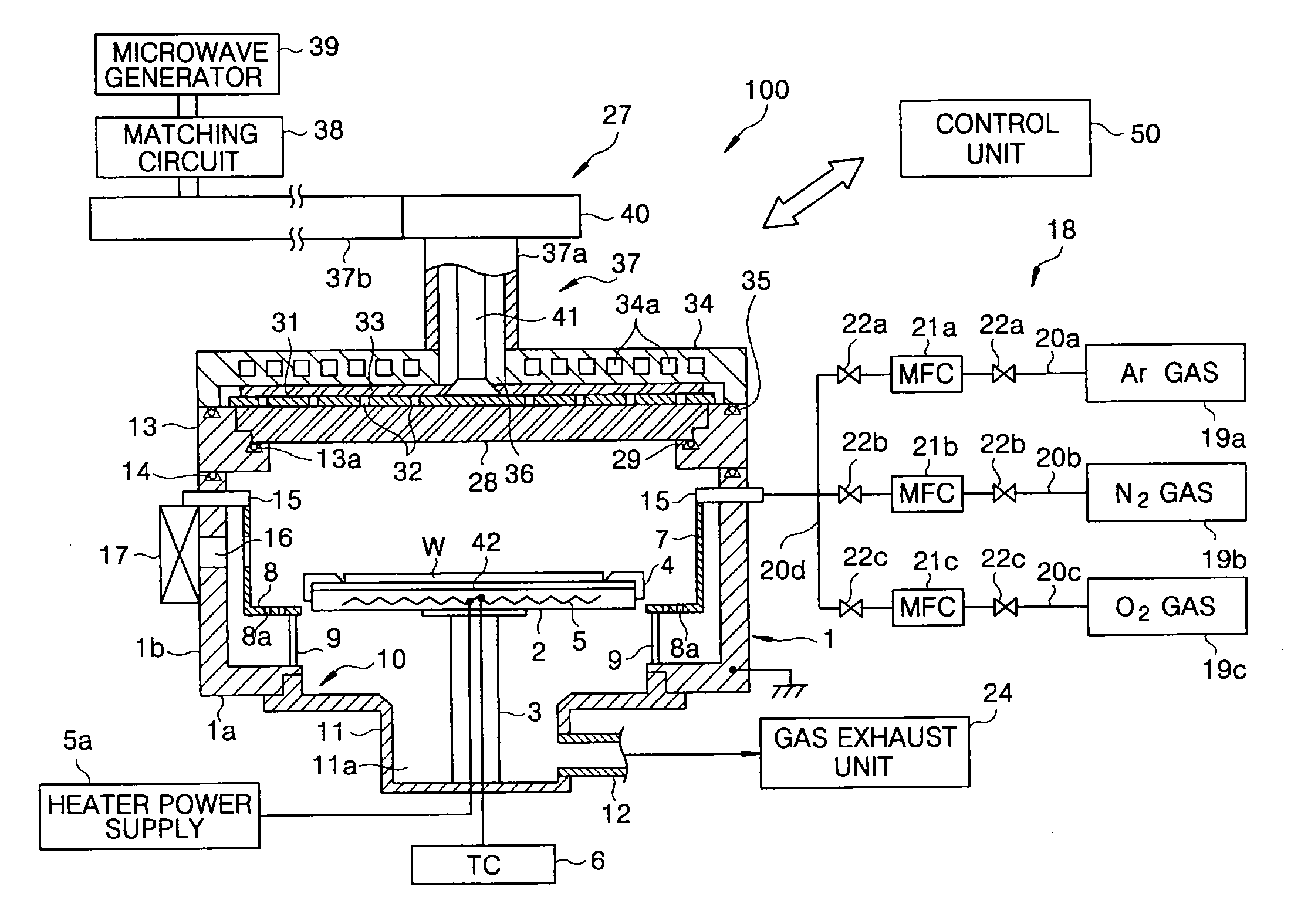
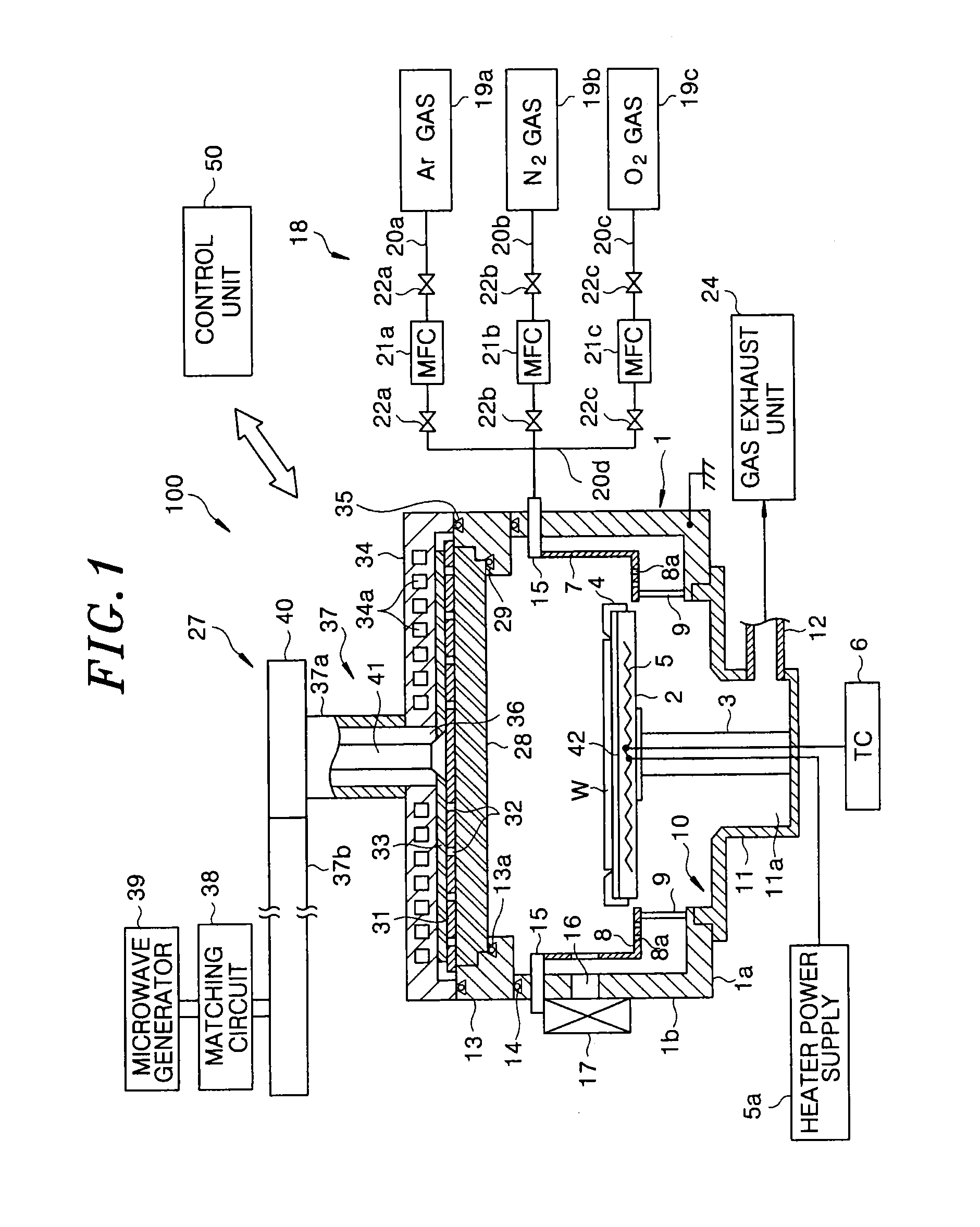
[0028]First, a configuration of a plasma nitriding apparatus that may be used in the plasma nitriding method in accordance with the embodiment of the present invention will be described with reference to FIGS. 1 to 3. FIG. 1 is a cross-sectional view schematically showing a configuration of the plasma nitriding apparatus 100. FIG. 2 is a plan view showing a planar antenna of the plasma nitriding apparatus 100 shown in FIG. 1. FIG. 3 shows a configuration of a control system of the plasma nitriding apparatus 100.

[0029]The plasma nitriding apparatus 100 is configured as an RLSA (Radial Line Slot Antenna) microwave plasma processing apparatus capable of generating a microwave-excited plasma with a high density and a low electron temperature in a processing chamber by introducing a...


PUM

PropertyMeasurementUnit
pressureaaaaaaaaaa
poweraaaaaaaaaa
poweraaaaaaaaaa

Abstract

A plasma nitriding method includes performing a high nitrogen-dose plasma nitriding process on an object having an oxide film by introducing a processing gas containing a nitrogen gas into a processing chamber of a plasma processing apparatus and generating a plasma containing a high nitrogen dose; and performing a low nitrogen-dose plasma nitriding process on the object by generating a plasma containing a low nitrogen dose. After the performing the high nitrogen-dose plasma nitriding process is completed, a plasma seasoning process is performed in the chamber by generating a nitrogen plasma containing a trace amount of oxygen by introducing a rare gas, a nitrogen gas and an oxygen gas into the chamber and setting a pressure in the chamber in a range from about 532 Pa to 833 Pa and a volume flow rate ratio of the oxygen gas in all the gases in a range from about 1.5% to 5%.

Description

FIELD OF THE INVENTION[0001]The present invention relates to a plasma nitriding method.BACKGROUND OF THE INVENTION[0002]A plasma processing apparatus for performing a process such as film formation or the like by using a plasma is employed in a manufacturing process of various semiconductor devices fabricated on, e.g., a silicon semiconductor or a compound semiconductor, a FPD (Flat Panel Display) represented by a liquid crystal display (LCD), and the like. In this plasma processing apparatus, a component made of a dielectric material such as quartz or the like is widely used for a component in the processing chamber. For example, there is known a microwave-excited plasma processing apparatus for generating a plasma by introducing a microwave into a processing chamber through a planar antenna having a plurality of slots. This microwave-excited plasma processing apparatus is configured to generate a high-density plasma by exciting a processing gas by an electric field generated in th...

Claims


Application Information

Patent Timeline
Patent Type & Authority Applications(United States)
IPC IPC(8): C23C16/22H05H1/46
CPCH01J37/32192H01J37/3222H01L21/0234H01L21/02332H01J2237/3387
Inventor DEBARI, TOSHINORISANO, MASAKI
Owner TOKYO ELECTRON LTD
Why Eureka
Try Eureka