Method and apparatus for generating and analyzing ions

a technology of applied in the direction of instruments, particle separator tube details, separation processes, etc., to achieve the effect of high ionization and ion transmission efficiency

Active Publication Date: 2013-01-31
SHIMADZU RES LAB SHANGHAI
View PDF6 Cites 25 Cited by
  • Summary
  • Abstract
  • Description
  • Claims
  • Application Information

AI Technical Summary

Benefits of technology

[0009]The current invention involves a method and an apparatus which provide high ionization and ion transmission efficiency in a low pressure region while at the same time maintain the convenience of direct analysis by desorbing samples under the ambient conditions.
[0013]Due to using the technology described above, this invention has the following advantages compared to the currently available technology:

Problems solved by technology

Thirdly, the apparatus contains a low pressure chamber where the neutral molecules are transferred to and are post-ionized.

Method used


Image

  • Method and apparatus for generating and analyzing ions
  • Method and apparatus for generating and analyzing ions
  • Method and apparatus for generating and analyzing ions

Examples


first embodiment

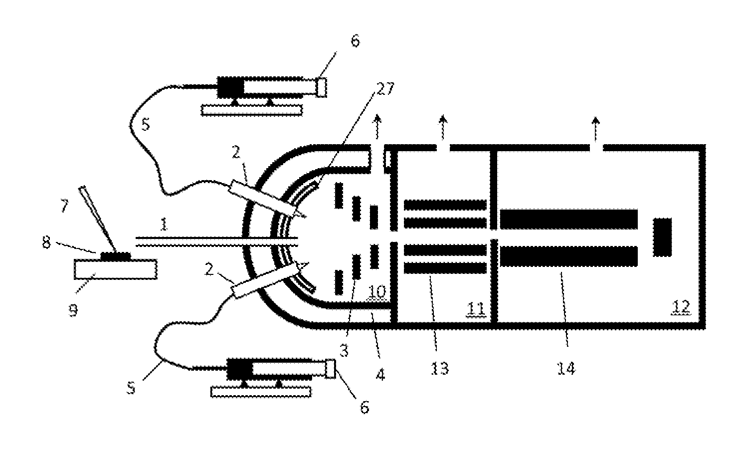
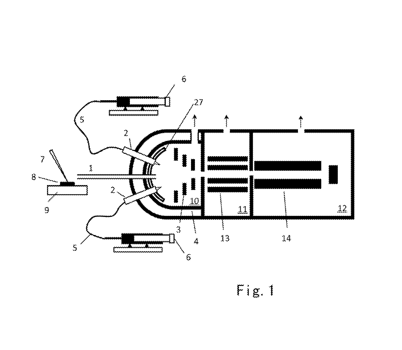
[0030]FIG. 1 shows the invention. The purpose of this embodiment is to perform sample desorption in the atmospheric pressure, LP-ESI, and mass analysis of the generated ions. In this embodiment solid sample 8 is placed on a sample substrate 9 located outside the vacuum and is subject to desorption by a beam of laser 7. As an alternative, the desorption process can also be achieved by means such as hot gas or ultrasonic vibration. The desorbed sample molecules are then transferred into a low pressure chamber 10 where the gaseous neutral molecules wound encounter a sprayed mist from the tip of a low pressure ESI probe 2. The solvent used for the LP ESI is provided by the syringe pump 5 and is introduced by the capillary 6. The pressure in the low pressure chamber 10 is preferred to be between 10 to 14000 Pa. The ESI probe 2 used here is preferred to be a nanospray probe where the i.d. of the spray capillary is preferred to be smaller than 10 micron and the flow rate is preferred to be...

third embodiment

[0035]For those analytes with high ionization energy, the photon energy of the vacuum UV may still not be enough. Therefore occasionally the post-ionization of analytes will rely on a charge transfer process with the assistance of dopant ions. As shown in FIG. 3, the dopant gas from the dopant gas container 26 can be brought into the first chamber 10 along with the desorbed analyte molecules and ambient air molecules. The intermediate pressure used in the first chamber 10 of the current invention is advantageous since dopant molecules can still exist in it with a relatively high concentration while keeping a long path length for the VUV photons. Note that the dopant gas from the dopant gas container 26 will enter the first chamber 10 together with the desorbed analyte molecules, the number of the dopant gas molecules is estimated to be counted for half of the gas molecules in the first chamber 10, namely there are about 1013 / cm3 dopant molecules at the pressure of 130 Pa. the curren...

fourth embodiment

[0036]the current invention involves directly coupling the inlet capillary 1 of the first chamber 10 with a gas or liquid source. In this case the desorption source is replaced with a nano-LC 29 where the liquid analytes from within can enter the first chamber 10 through the heated transfer line 30 (FIG. 6). The purpose of using the heated transfer line is to vaporize the LC effluents so that the neutral gas molecules can be obtained in the first chamber 10. For those effluents that are difficult to evaporate, one can also use photo irradiation, ultrasonic vibration, or high flow of hot gas to generate neutral molecules in the ambient air. In this embodiment both ionization means can also be used at the same time. In the mean time, a gas chromatograph or a reaction chamber can be directly connected to the capillary inlet 1 where the exit of the gas inlet can be considered as the sample stage. The only difference between the interface of GC / reaction chamber and that of LC is that the...


PUM

PropertyMeasurementUnit
pressureaaaaaaaaaa
pressureaaaaaaaaaa
pressureaaaaaaaaaa

Abstract

The current invention involves a method and a device for generating and analyzing ions in order to analyze samples directly without sample preparation. The gaseous neutral molecules are desorbed under atmospheric pressure by a desorption method. The desorbed neutral molecules are then transferred into a low pressure region where they are post-ionized by a mist from an electrospray probe tip or by photons from a vacuum UV source. The generated ions are then focused in a time varying electric field in the low pressure chamber before they are transferred into a mass spectrometer or ion mobility spectrometer for further analysis.

Description

FIELD OF THE INVENTION[0001]This invention relates generally to a process for generating and analyzing ions, and more particularly to a method and a device for generating and ionizing gaseous neutral molecules in a low pressure region.BACKGROUND OF THE INVENTION[0002]Years after mass spectrometry served as an extremely useful analytical technique in many different fields, ionization process still remains to be one of the most important techniques for meeting the increasingly demanding applications. Matrix-assisted laser desorption / ionization (MALDI, Rapid Commun. Mass Spectrom. 1988, 2, 151) and electrospray ionization (ESI, Science 1989, 246, 64) are the two techniques signifying the emergence of the mass spectrometry in wide spread biological applications. Both methods along with other mature ionization methods operated for solid or liquid require careful treatment of the sample before ionization.[0003]Therefore, the ionization methods for rapid detection without sample pretreatme...

Claims


Application Information

Patent Timeline
Patent Type & Authority Applications(United States)
IPC IPC(8): H01J49/26H01J49/04H01J49/16G01N27/622
CPCH01J49/066G01N27/622H01J49/10H01J49/24H01J49/164H01J49/165H01J49/161
Inventor KUMASHIRO, SUMIOSUN, WENJIANDING, LI
Owner SHIMADZU RES LAB SHANGHAI
Why Eureka
Try Eureka