
Radiation imaging system

a radiation imaging and system technology, applied in the field of radiation imaging systems, can solve the problems of limited number of direct conversion photoconductors that can be used for commercial products, limited number of direct conversion photoconductors can be used, and selenium having a atomic number of 34 only has good x-ray absorption,

Active Publication Date: 2013-02-07
VIEWORKS
View PDF3 Cites 9 Cited by
  • Summary
  • Abstract
  • Description
  • Claims
  • Application Information

AI Technical Summary

Benefits of technology

The patent describes a radiation imaging system that includes a layer for a radiation converter made of a layer of organic material containing a charge transport material and scintillating particles. The scintillating particles absorb the radiation and convert it into light. The light is then detected by a pixel unit. The system also includes a charge generation material that is in contact with the charge transport material. The charge generation material may be a quinolone or other similar material. The system may also include a charge injection blocking layer and a charge collection electrode for collecting the charge signals. The technical effects of this system include improved image quality and reduced noise.

Problems solved by technology

However, currently, only very limited number of direct converting photoconductors can be used for commercial products.
However, selenium having an atomic number of 34 has only good x-ray absorption in the low energy range, typically below 30 Kev.
Since the complication and difficulty of fabrication of good imaging quality amorphous selenium is a strong function of the selenium thickness, successful x-ray imaging product so far are limited to lower energy x-ray application such as mammography, low energy x-ray crystallography, low energy non-destructive testing.
However, because of the scattering of the scintillation, this type of indirect conversion x-ray detector has a high point spread function resulting with a lower spatial resolution in compared to the direct conversion type such as selenium.

Method used


Image

  • Radiation imaging system
  • Radiation imaging system
  • Radiation imaging system

Examples


examples

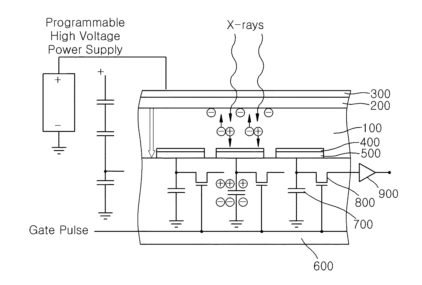
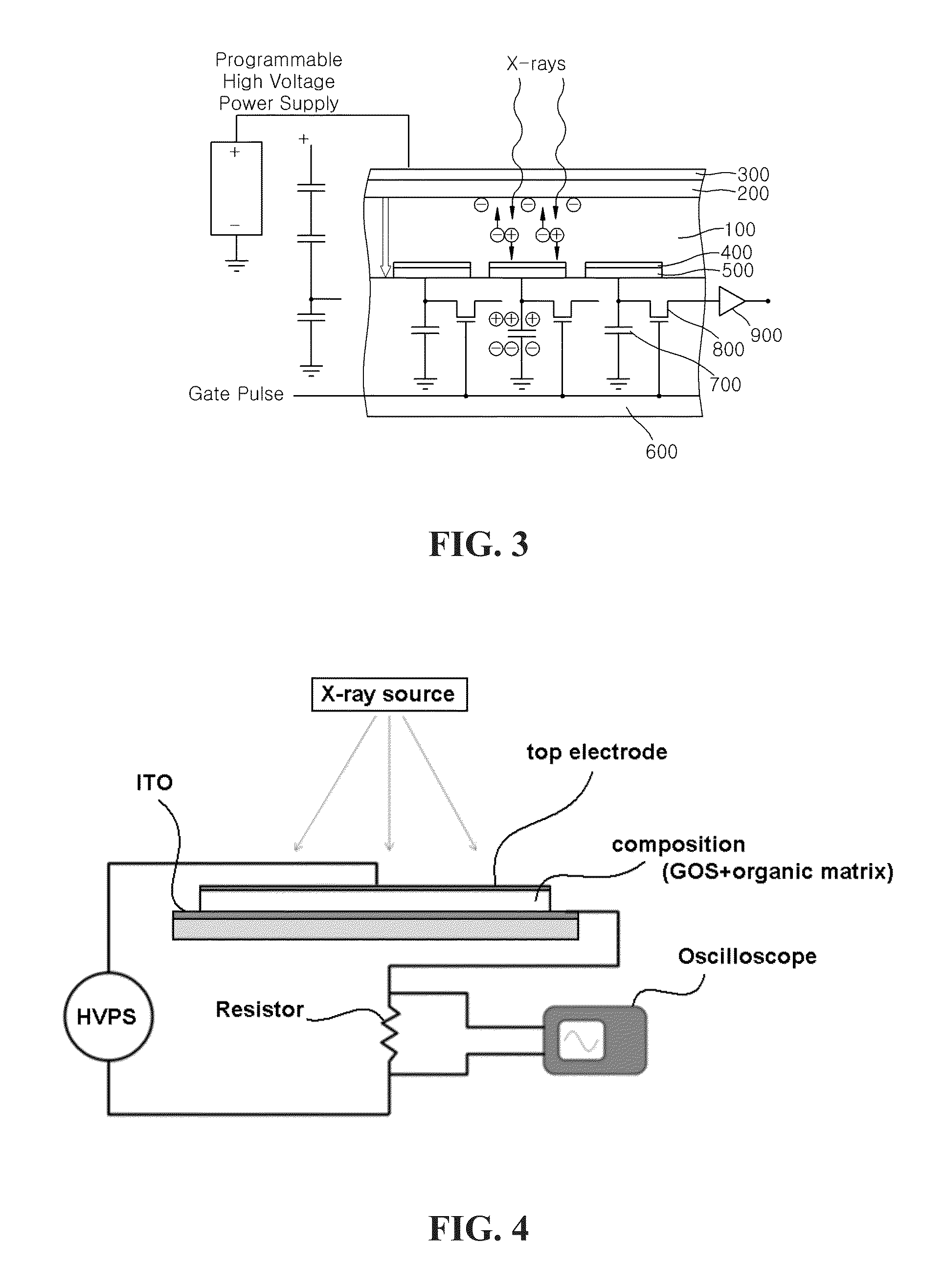
[0073]Methylene chloride and toluene are mixed with 10:1 weight ratio to prepare a solution. Then, 2% weight of oxytitanium phthalocyanine having the chemical formula 1 as CGM, 2% weight of 4,4′-TPD (Triphenylamine Dimer) having the chemical formula 2 as CTM, 2% weight of Polycarbonate polymer are added to the solution to obtain a mixture. The weight ratio of CGM, CTM and Polycarbonate is 1:1:1. 20 g of Europium doped GOS powder having a diameter of 4 μm is added to 4 ml of CGM / CTM mixture plus 0.54 ml of toluene to prepare a composition. The composition is then coated onto an indium tin oxide (ITO) bottom electrode using a doctor blade with a thickness of 500 μm. After 48 hours of curing at a temperature of 50° C., a conductive top electrode is coated to the top surface of the composition. A bias voltage is applied to the top electrode of the sample and the ITO bottom electrode is connected to a load resistor R with return circuit to the high voltage power supply. An oscilloscope p...


PUM


Abstract

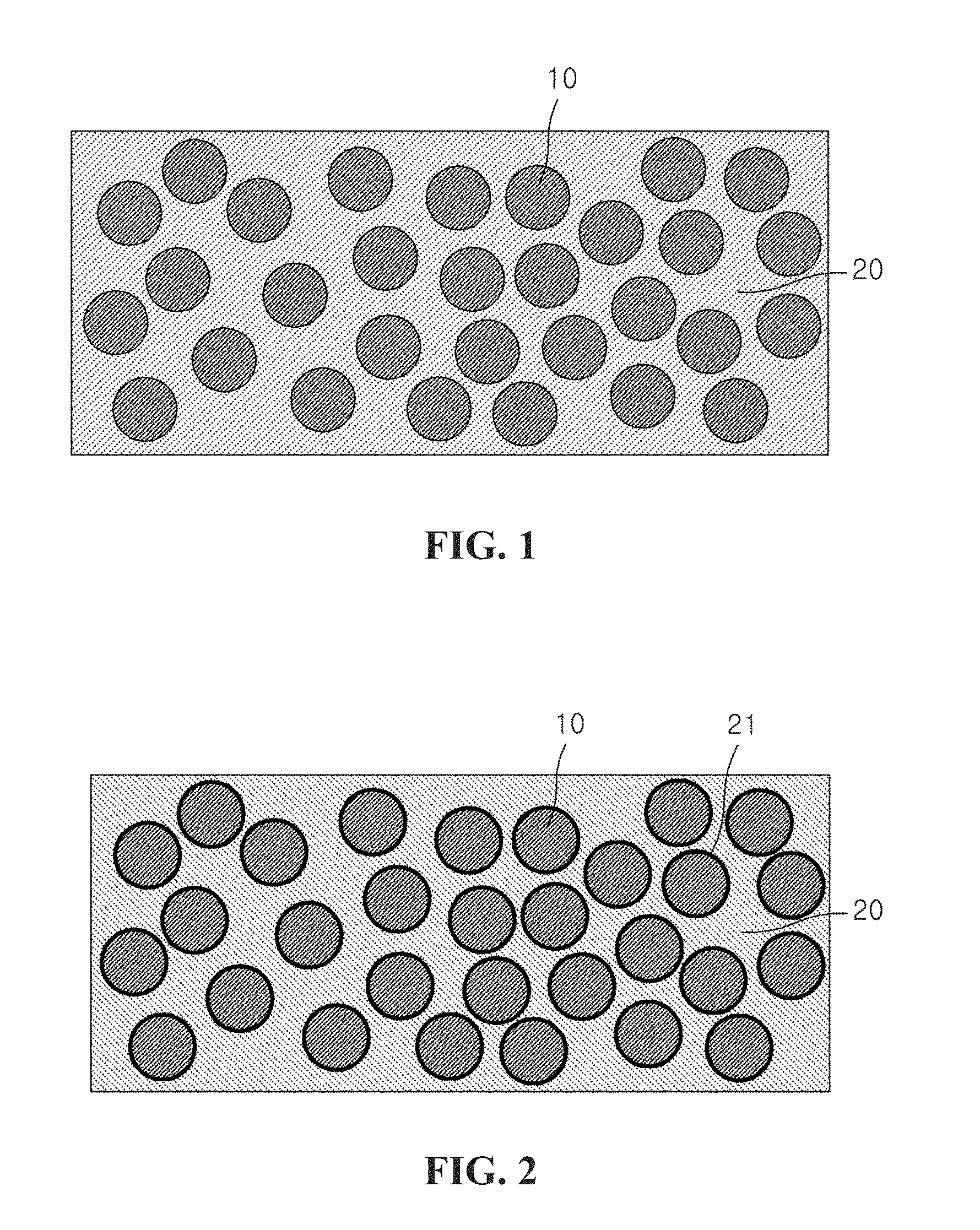
Disclosed is a radiation imaging system comprising a layer for a radiation converter; a top electrode on the layer for a radiation converter; and an array of pixel unit electrically coupled to the layer for a radiation converter; wherein, said layer for a radiation converter comprises an organic matrix comprising a charge transport material (CTM); and scintillating particles for absorbing radiation, being dispersed in the organic matrix, wherein the scintillating particles are in contact with a charge generation material (CGM).

Description

CROSS-REFERENCE TO RELATED APPLICATIONS[0001]This application claims the benefit of U.S. Provisional Patent Application Nos. 61 / 514,089, filed Aug. 2, 2011, 61 / 514,116, filed Aug. 2, 2011, and 61 / 514,121, filed Aug. 2, 2011, which are hereby incorporated by reference in their entirety.FIELD OF THE INVENTION[0002]The present invention relates to a radiation imaging system. More particularly, the present invention relates to a radiation imaging system using a novel composition as a layer for a radiation converter which absorbs radiation and subsequently producing electrical charges proportional to the absorbed radiation.BACKGROUND[0003]Traditional medical diagnostic processes record X-ray image patterns on silver halide films. These systems direct an initially uniform pattern of interrogating X-ray radiation through a patient to be studied, intercept the consequently image-wise modulated pattern of X-ray radiation with an X-ray radiation intensifying screen, record the intensified pat...

Claims


Application Information

Patent Timeline
Patent Type & Authority Applications(United States)
IPC IPC(8): G01T1/20
CPCG01T1/20G01T1/24C09K11/616C09K11/628C09K11/682H01L27/14676C09K11/7774G21K4/00G21K2004/06G21K2004/08H01L27/14665C09K11/7701
Inventor LEE, DENNY LAP YENJANG, HYUN SUK
Owner VIEWORKS
Learn More