
Organic electronic material, polymerization initiator and thermal polymerization initiator, ink composition, organic thin film and production method for same, organic electronic element, organic electroluminescent element, lighting device, display element, and display device

a technology of organic electronic elements and initiators, applied in the direction of non-metal conductors, group 5/15 element organic compounds, conductors, etc., can solve the problems of low light emission efficiency and short element service life, difficult multilayering in polymer type organic el elements, and low light emission efficiency. , to achieve the effect of enhancing the productivity of organic electronic elements, reducing driving voltage, and prolonging the life of light emission

Active Publication Date: 2013-02-14
RESONAC CORP
View PDF12 Cites 17 Cited by
  • Summary
  • Abstract
  • Description
  • Claims
  • Application Information

AI Technical Summary

Benefits of technology

The present invention provides an organic electronic material that can easily form a thin film, has high solubility, and can be easily multilayered, which is useful for enhancing the productivity of organic electronic elements, particularly polymer type organic EL elements. Additionally, the material contains an ionic compound which results in organic electronic elements and organic EL elements with lower driving voltage and longer light emission lifetime than conventional elements.

Problems solved by technology

Active research has been hitherto conducted in relation to low molecular weight organic EL elements as well as polymer type organic EL elements; however, low light emission efficiency and short element service life still remain as serious problems.
On the other hand, since film formation is carried out by using a wet process such as printing or inkjetting in a polymer type organic EL element, there is a problem that when an upper layer is applied, the lower layer is dissolved out.
Therefore, multilayering in a polymer type organic EL element is difficult to achieve as compared in a low molecular weight organic EL element, and the effects of enhancing the light emission efficiency and improving the service life may not be obtained.
These methods for promoting multilayering are important; however, there are problems that when water-soluble PEDOT:PSS is used, it is necessary to remove any moisture remaining in the thin film, that when it is attempted to utilize the difference in solubility, there are limitations on the materials that can be used, or that the siloxane compound is unstable to moisture in air.
Also there is a problem that the element characteristics are not satisfactory.
However, these literatures lack descriptions on an organic electronic material which uses a photoacid generator or initiator containing fluorine atoms.

Method used


Image

  • Organic electronic material, polymerization initiator and thermal polymerization initiator, ink composition, organic thin film and production method for same, organic electronic element, organic electroluminescent element, lighting device, display element, and display device
  • Organic electronic material, polymerization initiator and thermal polymerization initiator, ink composition, organic thin film and production method for same, organic electronic element, organic electroluminescent element, lighting device, display element, and display device
  • Organic electronic material, polymerization initiator and thermal polymerization initiator, ink composition, organic thin film and production method for same, organic electronic element, organic electroluminescent element, lighting device, display element, and display device

Examples


synthesis example 2

Ionic Compound Synthesis Example 2

[0141]Synthesis was carried out in the same manner as in Ionic Compound Synthesis Example 1, except that potassium tris(trifluoromethanesulfonyl)methide of the Ionic Compound Synthesis Example 1 was replaced with lithium bis(trifluoromethanesulfonyl)imide. A target ionic compound B was obtained as a yellow powder. Yield: 85.9%.

[0142]The reaction scheme of this Synthesis Example is shown below.

synthesis example 3

Ionic Compound Synthesis Example 3

[0143]Potassium tris(trifluoromethanesulfonyl)methide (0.57 g, 1.34 mmol) was introduced into a pear-shaped flask, and the compound was dissolved in ethyl acetate (10 mL). An ethyl acetate solution (10 mL) of diphenyliodonium hexafluorophosphate (0.60 g, 1.33 mmol) was slowly added dropwise to the solution, and the mixture was stirred for one hour at room temperature. The organic layer was thoroughly washed with water, and then the solvent was distilled off. Thus, 0.90 g of a target ionic compound C was obtained as a white powder. Yield: 97.0%.

[0144]The reaction scheme of this Synthesis Example is shown below.

synthesis example 4

Ionic Compound Synthesis Example 4

[0145]Synthesis was carried out in the same manner, except that potassium tris(trifluoromethanesulfonyl)methide of the Ionic Compound Synthesis Example 3 was replaced with lithium bis(trifluoromethanesulfonyl)imide. A target ionic compound D was obtained as a white powder. Yield: 89.8%.

[0146]The reaction scheme of this Synthesis Example is shown below.


PUM

PropertyMeasurementUnit
temperatureaaaaaaaaaa

Abstract

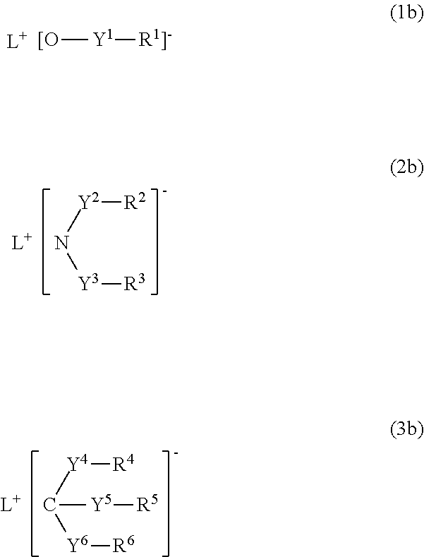
Disclosed is an organic electronic material comprising charge transporting compounds and ionic compounds having electron-accepting properties and high solubility in a solvent. The organic electronic material is characterized by comprising charge transporting compounds and ionic compounds, and in that at least one of the ionic compounds is any one kind of compounds represented by general formulas (1b)-(3b). (In the formulas Y1-Y6 each independently represent a divalent linking group, R1-R6 each independently represent an electron-attracting organic substituent (these structures can further have substituents and hetero-atoms, and R1, R2 and R3, or, R4-R6 can respectively combine and become a ring shape or a polymer shape) and L+ represents a monovalent cation.)

Description

TECHNICAL FIELD[0001]The present invention relates to an organic electronic material, a polymerization initiator and a thermal polymerization initiator, an ink composition, an organic thin film and a production method for the same, an organic electronic element, an organic electroluminescent element (hereinafter, also referred to as an organic EL element), a lighting device, a display element, and a display device.BACKGROUND ART[0002]An organic electronic element is an element which performs an electrical operation by using an organic substance, and is expected to be able to exhibit features such as energy saving, low price, and flexibility. Thus, organic electronic elements are attracting public attention as a technology that replaces conventional inorganic semiconductors containing silicon as a main component.[0003]Examples of the organic electronic element include organic EL elements, organic photoelectric conversion elements, and organic transistors.[0004]Among the organic elect...

Claims


Application Information

Patent Timeline
Patent Type & Authority Applications(United States)
IPC IPC(8): C07C317/04H01B1/12C07C309/39C07C309/06C07C311/09C07F9/54
CPCH01B1/122C08L65/00H01L51/0043H01L51/0085H01L51/5016H01L51/5036H01L51/5048H01L2251/308C09D11/52C08K5/42C08K5/435C08G2261/1412C08G2261/1644C08G2261/3142C08G2261/3162C08G2261/411C08G2261/512C08G2261/5222C08G2261/76C08G2261/95H01L51/0039H10K85/115H10K85/151H10K85/342H10K50/11H10K2101/10H10K50/125H10K50/14H10K2102/103H10K85/657
Inventor ISHITSUKA, KENICHIFUNYUU, SHIGEAKIHOSHI, YOUSUKE
Owner RESONAC CORP
Learn More