
Waveform distortion mitigation in power systems

a technology of power system and waveform, applied in the direction of harmonic reduction arrangement, ac network to reduce harmonics/ripples, transportation and packaging, etc., can solve the problems of compromising the integrity of the power grid, egregious limitation, and undesirable harmonic distortion of smpps into the power system, so as to reduce waveform distortion and reduce waveform distortion

Active Publication Date: 2013-02-14
GRUNEWALD CHARLES +2
View PDF7 Cites 19 Cited by
  • Summary
  • Abstract
  • Description
  • Claims
  • Application Information

AI Technical Summary

Benefits of technology

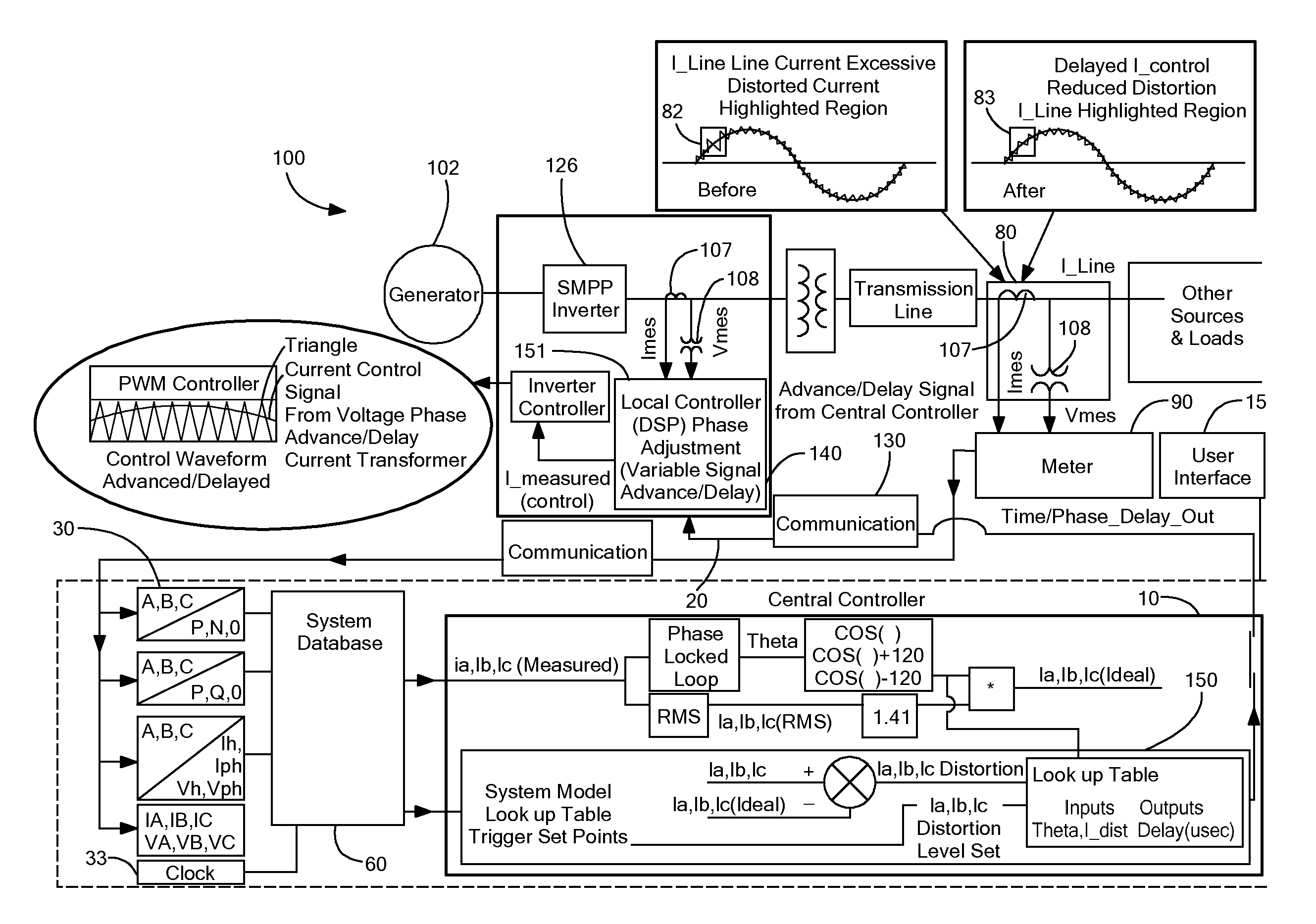
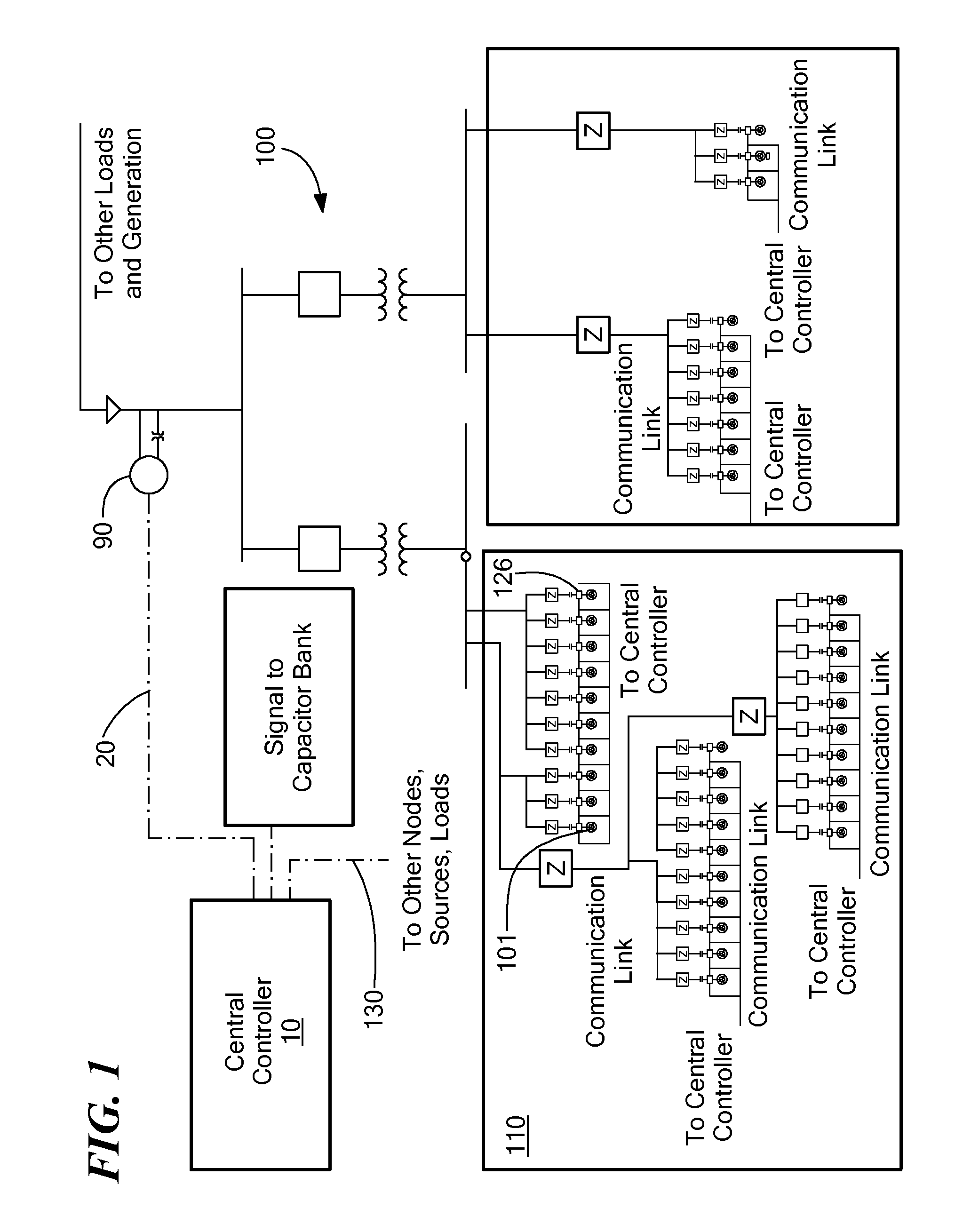
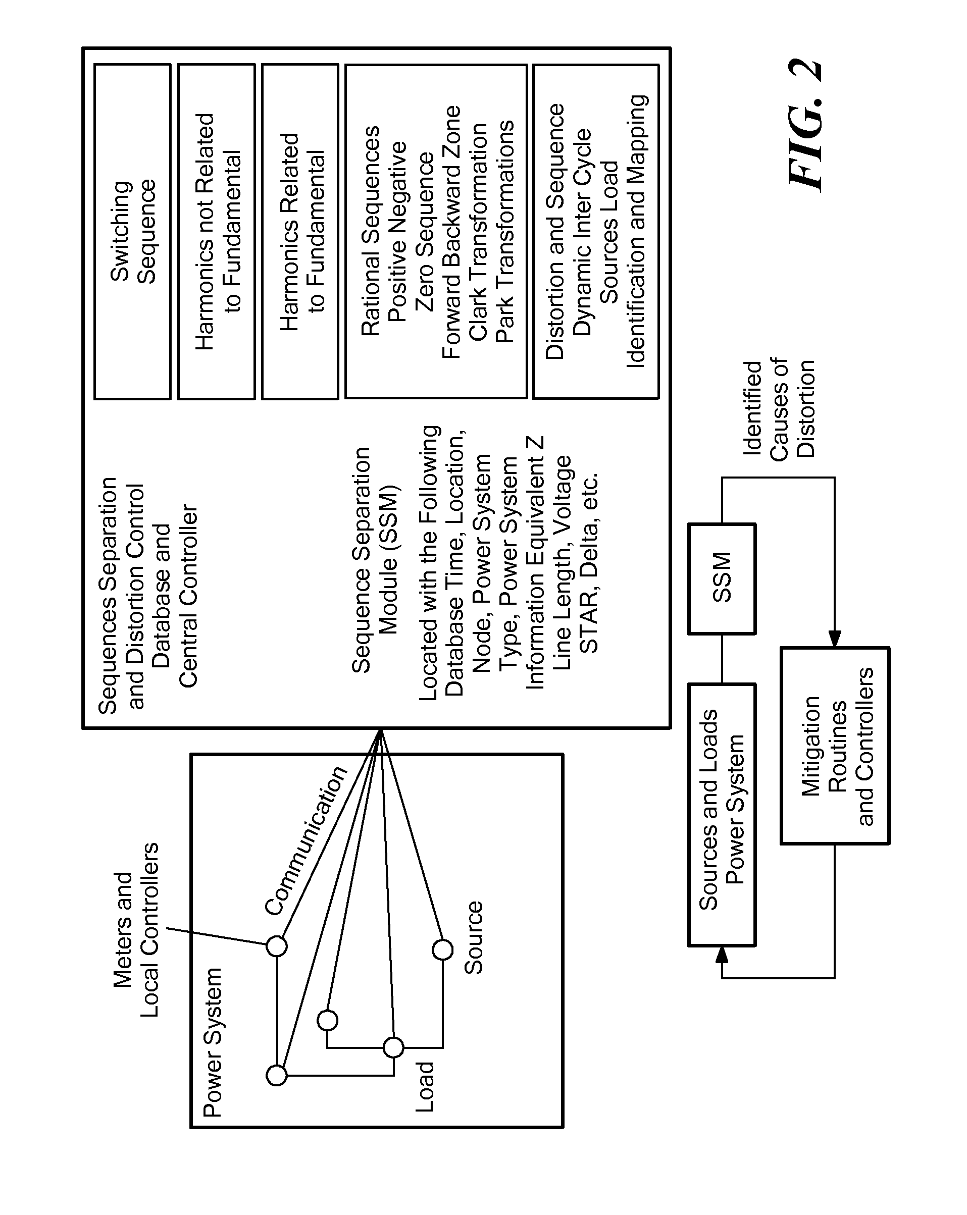
The present invention provides methods and systems for governing harmonic content in a power transmission system. The methods involve monitoring current and voltage at multiple locations on the system and characterizing the monitoring data relative to specified constraints. When there is a deviation in the monitoring data, the methods modify the voltage and current by changing at least one of time delay or phase characteristics of the system's elements. The methods can be applied to both polyphase AC and DC power transmission systems. The systems include a database for storing measures of waveform distortion and a processor for identifying the node where a solution reducing waveform distortion can be applied. The systems also have a waveform adjustor that can introduce time delay or change the phase of signals within the system. The technical effects of the invention include improved harmonic content control, reduced waveform distortion, and improved power transmission efficiency.

Problems solved by technology

SMPPs can produce undesirable harmonic distortion into the power system.
Despite adherence to the aforesaid standard, there is evidence that multiple SMPPs can collectively construct undesirable and potentially damaging harmonic distortion that may compromise the integrity of the power grid.
Various methods have been employed for reduction of harmonic content on polyphase power systems, however all of them are limited in that they eliminate only a particular class of harmonics (namely, integral multiples of the AC fundamental), and in that each is capable of being applied only at a single node of a power system.
The fact that the prior art applies harmonic mitigation only at a local, single point, is a particularly egregious limitation in the case of wind power.
Similarly, while it already known how to determine the impact of non-linear load harmonics on voltage distortion at a point of common coupling, such techniques are limited to singular points within a system, and do not characterize the system in its entirety.
Thus, for example, dynamic harmonic filters are known in the context of AC power systems, however they only monitor, and improve performance at, specific single points on the system.
Currently practiced techniques are prone to damage both utility and customer equipment, as suggested, in the context of transformers in Parthemore, et al., “Gassing in Wind-Farm Transformers,”Windpower Eng.
Currently, waveform distortion causes premature aging of electrical equipment, excessive heating, current and voltage stresses that cause failure in electrical components, loss of real power production and consequently loss of revenue.
On polyphase AC power systems and DC power systems, distortion of the desired signal has consequences.
In the past, power systems engineers called this “harmonic distortion.” The problem is larger however, and encompasses all manner of signal distortion.
However, harmonic analysis is deficient in modern power systems and, even though switch mode power supplies and other modern piecewise or nonlinear elements are mentioned in IEEE 519, the standard is brief and insufficient on characterizing their behavior on the power system.
These newer topologies, such as switch mode power processors, produce distortion that is not a whole number multiple of the fundamental frequency on the power system
Another deficiency in the current state of the art and existing processes is that, typically, signal distortion is handled only in the planning phases of a power system that is to be modified or a new power system.
This process uses models of the power system to predict what the harmonic impact will be and does not assess the actual or measured impact.
Yet another deficiency in the state of the art of harmonic distortion is that harmonic distortion is predicated on whole number multiples of the fundamental frequency on the power system.
However, new switch mode power supplies placed either on the load or the sources do not always distort the signal at a whole number multiple of the fundamental frequency.
Consequently, current state of the art of harmonic analysis is incomplete when attempting to consider all the causes of signal distortion.
However, in reality this is not the case.
Most electrical equipment will create distortion in the waveforms.
The signal distortion can be problematic because it may damage, age, or reduce efficiency of equipment within the power system.
However with new distributed generation power plants such as wind farms, which use switch mode power processors, plant operators have found old methods do not work as well as they did in the past.
However, in order to create these desired waveforms, the algorithms and PWM switching equipment will take an ideal waveform signal and distort it.
It has been observed that the magnitude of the distortion decreases as the frequency increases, but this is not always the case.
In distributed generation and in distributed loads which use switch mode power supplies or power processors the distortion can add up at common location on the power system and the resulting distortion at higher frequencies may become unacceptable.
However SMPPs can only approximate the ideal wave form for the load, often by replicating a template wave-form sampled from the grid to which it is connected.
Consequently, these imperfect wave forms created by SMPPs contribute to the overall distortion.
However, the converse is equally true since they are not coordinated and may constructively increase the level of distortion.
Currently, there exists no mechanism to know when or where the distortion may add up beyond acceptable standards since there are no standard measurements analyses that would capture these phenomena in their entirety.
Because of their considerable power ratings, three-phase SMPPs may be the main contributors to the distortion problem.
Signal distortion and harmonics on the power system can damage wind turbine generators in a multitude of ways.
As one example, the problem of over voltage saturation is particularly damaging to transformers and wind turbine generators.
Other higher order harmonics that combine in a similar nature will also produce damage to the drive train.
The issue with this is that the picture is static and not fluid.
The existing methods of analyses do not include traveling waves on the power system; nor do they consider the signal propagation delays through plants and controllers.
One salient limitation of contemporary harmonic analysis is that it does not consider traveling waves and signal propagation delay(s) within the control system or distributed control system.
One problem resulting from this is that an engineer does not have an idea of what is causing the harmonic or, better stated, signal distortion, since we know harmonic analysis is limited in the first place, and unless it is a usual cause that can be easily identified, the engineer is unable to arrive at a determinate solution.
Sometimes they add up to increase in amplitude and create an impulse on the power system that can be damaging to equipment.
Currently, SMPP controllers are not coordinated to handle this issue.
Each controller on its own will have low signal distortion, however, since they are in phase at a particular node, a signal distortion may increase or be compounded.
The aggregate effect is that the magnitude of a given frequency has increased and is damaging equipment.
However, the aligning of the distributed control systems is transitory in nature and constructively aligns or destructively interferes, thus hiding itself from engineers and technicians, and reoccurring when conditions enable rogue wave construction.
This signal distortion of the voltage is added to the existing distortion on the transmission system.
Due to the complex nature of the power system, collector system, and distributed generator (DG) controls, it is difficult to identify how and when the distortion problems will construct or occur.

Method used


Image

  • Waveform distortion mitigation in power systems
  • Waveform distortion mitigation in power systems
  • Waveform distortion mitigation in power systems

Examples


Embodiment Construction

[0068]Embodiments of the present invention described herein relate generally to improving power system conditions and, more specifically, to a characterization of harmonics and underlying causes for improvement of a waveform on a power system in order to reduce distortion of waveforms on polyphase AC and DC power systems. Embodiments of the present invention may be employed advantageously to improve system efficiency, power transfer reliability, and longevity of equipment, as well as to prevent premature aging or damage to electrical equipment that is part of a power system or that is coupled to the power system.

[0069]Embodiments in accordance with the present invention, as described in detail below, provide real time and archived characterization of the power system and the characterization of signal distortion by defining sources and loads at the frequency at which they occur and not characterizing a source as just as source but defining where the source is acting at as load at a ...


PUM


Abstract

Systems and methods for governing a signal waveform of a signal flowing through a component of a power transmission system that includes a plurality of switch-mode power processors and may be a polyphase system. At least one of current and voltage is integrally monitored at each of a plurality of locations on the power system and is characterized relative to specified constraints. When a monitored voltage or current is outside of the specified constraints, the voltage or current is modified by changing at least one of the time delay or phase characteristics of at least one of the source, load and transmission elements on the power transmission system.

Description

[0001]The present application claims priority from U.S. Provisional patent Application Ser. No. 61 / 488,264, filed May 20, 2011, and incorporated herein by reference.[0002]A portion of the disclosure of this patent document contains material which is subject to copyright protection, and the present notice is provided in accordance with 37 CFR 1.71(e). The copyright owner has no objection to the facsimile reproduction by anyone of the patent document or the patent disclosure, as it appears in the Patent and Trademark Office patent file or records, but otherwise reserves all copyright rights whatsoever.TECHNICAL FIELD[0003]The present invention pertains to devices and methods for modifying waveform content in power systems, and, more particularly, to devices and methods for modifying waveform distortion in polyphase AC and DC power equipment.BACKGROUND OF THE INVENTION[0004]Deployment of distributed power generation such as wind and solar power continues to grow. Most of these power sy...

Claims


Application Information

Patent Timeline
IPC IPC(8): H02J4/00
CPCH02J3/01H02J3/18H02J13/0079Y02E40/74Y02E40/40Y04S10/22Y02E40/30H02J13/00028H02J13/00034Y02E40/70
Inventor WILKINS, THOMAS ALEXANDERHALLER, MARK E.GRUNEWALD, CHARLES
Owner GRUNEWALD CHARLES
Learn More