Resin composition for printed circuit board

a technology of printed circuit board and composition, which is applied in the direction of synthetic resin layered products, solid-state devices, woven fabrics, etc., can solve the problems of deterioration in the accuracy of forming fine circuits, deterioration of position accuracy and adhesion strength of circuits, and the tendency of projecting parts to remain on the resin surface of the lamina

Inactive Publication Date: 2013-02-14
MITSUBISHI GAS CHEM CO INC
View PDF3 Cites 5 Cited by
  • Summary
  • Abstract
  • Description
  • Claims
  • Application Information

AI Technical Summary

Benefits of technology

[0016]The resin composition according to the present invention has at least one of the following effects:(1) It is highly soluble and easily handleable;(2) It can provide good plate / copper adhesion even when the surface roughness is low.(3) It exhibits high thermal resistance under moisture absorption.
[0017]Thanks to the effects of items (1) to (3) above, the resin composition of the present invention is suitable for use as a resin in high-density printed-wiring boards.

Problems solved by technology

When fine circuits are formed, projecting parts are prone to remain on the resin surface of the laminate due to the remarkable unevenness of the matte surface.
However, there is a problem in that complete removal of the residual projections may bring about over etching of circuits, causing deterioration in positional accuracy and adhesion strength of circuits.
However, there is a problem in that such increased surface unevenness may cause deterioration in accuracy of forming fine circuits (see, e.g., Patent Documents 1 and 2).
In addition, polyimide for use as a resin for metallic foil-clad wiring boards is often poorly-soluble to organic solvents and has difficulty in being made into varnish.
Further, a metallic foil-clad laminate using polyimide often has a problem in that when the metallic foil is etched and the conducting layer is formed thereon by plating, it exhibits poor thermal resistance under moisture absorption, causing swell of the plate due to heating after moisture absorption.
Moreover, in order to secure sufficient adhesion strength between the insulating layer and the conducting layer, the copper foil (matte) surface is required to have a certain degree of unevenness, making it difficult to reduce the roughness of the substrate surface.

Method used


Image

  • Resin composition for printed circuit board
  • Resin composition for printed circuit board
  • Resin composition for printed circuit board

Examples


synthetic example 1

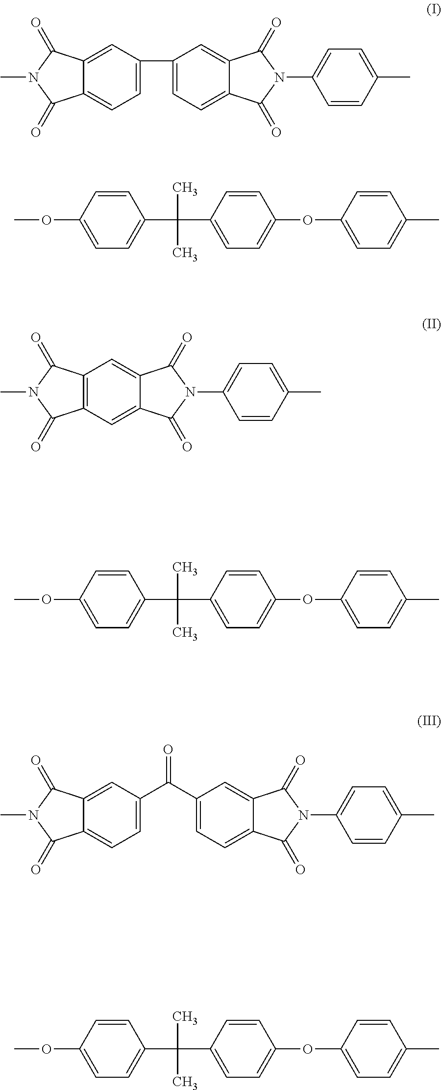
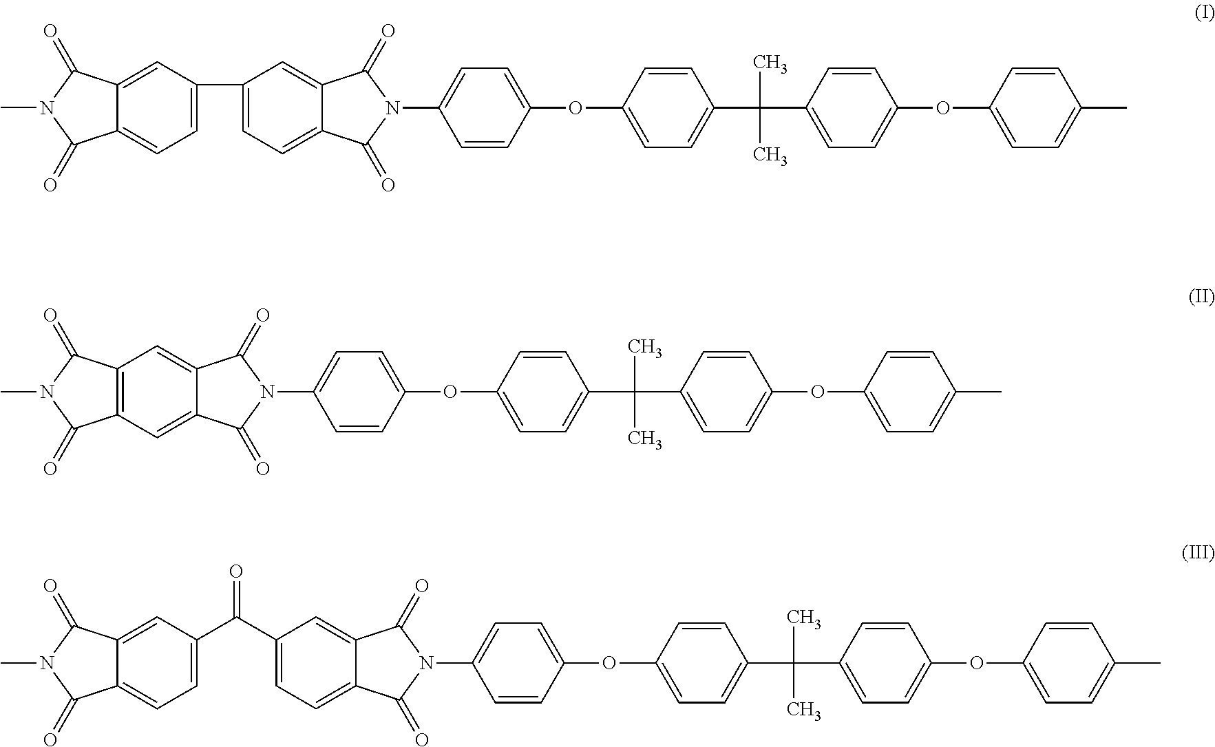
[0068]A four-necked 1000 ml flask equipped with stainless-steel agitating blades, nitrogen duct, a Dean-Stark with cooling tube, and a thermometer was loaded with 41.06 g (100 mmol) of 2,2-bis{4-(4-aminophenoxy)phenyl}propane (hereinafter called BAPP), 100 g of NMP, 12 g of toluene, and 0.51 g of triethylamine, and the content was agitated at 100 rpm under a nitrogen atmosphere. To the resultant solution, 2.18 g (10 mmol) of pyromellitic dianhydride (hereinafter called PMDA), 26.48 g (90 mmol) of 3,4,3′,4′-biphenyltetracarboxylic dianhydride (hereinafter called BPDA), and 100 g of NMP were added each in a mass, and the mixture was agitated at room temperature for one hour, and heated in oil bath for about 20 minutes until the temperature in the reaction system reaches 180° C. Distilled components were captured while the temperature in the reaction system was maintained at 180° C. for 30 minutes, after which the temperature in the reaction system was decreased to approximately 130° C...

synthetic example 2

[0069]A four-necked 1000 ml flask equipped with stainless-steel agitating blades, nitrogen duct, a Dean-Stark with cooling tube, and a thermometer was loaded with 32.85 g (80 mmol) of BAPP, 80 g of NMP, 6 g of toluene, and 0.41 g of triethylamine, and nitrogen under atmosphere, 100 rpm the content was agitated at 100 rpm under a nitrogen atmosphere. To the resultant solution, 5.23 g (24 mmol) of PMDA, 16.48 g (56 mmol) of BPDA, and 80 g of NMP were added each in a mass, and the mixture was agitated at room temperature for one hour, and heated in oil bath for about 20 minutes until the temperature in the reaction system reaches 180° C. Distilled components were captured while the temperature in the reaction system was maintained at 180° C. for 30 minutes, after which the temperature in the reaction system was decreased to approximately 130° C. The reaction system was then mixed with 405.0 g of NMP under agitation to form a homogenous solution, and air-cooled to almost reach room temp...

synthetic example 3

[0073]A four-necked 1000 ml flask equipped with stainless-steel agitating blades, nitrogen duct, a Dean-Stark with cooling tube, and a thermometer was loaded with 32.85 g (80 mmol) of BAPP, 80 g of NMP, 6 g of toluene, and 0.41 g of triethylamine, and the content was agitated at 100 rpm under a nitrogen atmosphere. To the resultant solution, 7.73 g (24 mmol) of 3,3′,4,4′-benzophenone tetracarboxylic dianhydride (hereinafter called BTDA), 16.48 g (56 mmol) of BPDA, and 80 g of NMP were added each in a mass, and the mixture was agitated at room temperature for one hour, and heated in oil bath for about 20 minutes until the temperature in the reaction system reaches 180° C. Distilled components were captured while the temperature in the reaction system was maintained at 180° C. for 30 minutes, after which the temperature in the reaction system was decreased to approximately 130° C. The reaction system was then mixed with 347 g of NMP under agitation to form a homogenous solution, and a...


PUM

PropertyMeasurementUnit
temperatureaaaaaaaaaa

Abstract

A resin composition is provided which comprises a polyimide resin, a thermosetting resin, and a filler, the polyimide resin containing a first repeat unit represented by formula (I) and a second repeat unit represented by formula (II) or (III), wherein when the second repeat unit is represented by formula (II), the ratio of the second repeat unit to the polyimide resin is between 5 and 35 mol %, and when the second repeat unit is represented by formula (III), the ratio of the second repeat unit to the polyimide resin is between 5 and 80 mol %.

Description

TECHNICAL FIELD[0001]The present invention relates to a resin composition and, more specifically, to a resin composition suitable for a printed-wiring board, as well as to a metallic foil-clad laminate and a printed-wiring board using the same.BACKGROUND ART[0002]In recent years, smaller, thinner and lighter electronics have been demanded, and the need for printed-wiring boards with higher density is also increasing. Densification of printed-wiring boards requires forming finer circuits. Conventional methods for forming circuits include subtractive method, in which a metallic foil is etched to form a circuit, and (semi)additive method, in which a conducting layer is formed on an insulating layer by plating.[0003]For the subtractive method, a metallic foil having a remarkably uneven matte surface is used to provide better adhesion to the insulating layer. When fine circuits are formed, projecting parts are prone to remain on the resin surface of the laminate due to the remarkable une...

Claims


Application Information

Patent Timeline
Patent Type & Authority Applications(United States)
IPC IPC(8): C08L79/08B32B15/08H05K1/03B32B5/02
CPCC08K3/0025C08G73/1071C08L101/00H01L23/145H05K1/0366H05K1/0373H05K3/022H05K2201/0209C08L79/08C08G73/105C08G73/1042B32B2457/08B32B5/022B32B5/024B32B15/08B32B15/088B32B2305/076H01L2924/0002C08J5/24C08J2300/24C08J2379/08C08J2400/24C08J2479/08C08K3/012Y10T428/31721Y10T428/31681Y10T442/20H01B3/306H01B3/307H01B3/40H01L2924/00C08G73/10H05K1/03
Inventor OOMORI, TAKABUMIHASEBE, KEIICHI
Owner MITSUBISHI GAS CHEM CO INC
Why Eureka
Try Eureka