Methods and Devices for Detecting Structural Changes in a Molecule Measuring Electrochemical Impedance

a technology of electrochemical impedance and structural change, applied in the field of biological molecules, can solve the problems of preventing dots from being formed below certain threshold sizes, problems arise, etc., and achieve the effects of reducing noise or spurious signals, reducing electrode diameter, and reducing the size of electrodes

Inactive Publication Date: 2013-02-14
UNIV OF LEEDS
View PDF4 Cites 1 Cited by
  • Summary
  • Abstract
  • Description
  • Claims
  • Application Information

AI Technical Summary

Benefits of technology

[0048]If is a further advantage of the invention that the release of compounds from those electrodes is advantageously permitted. This may be easily implemented by the individual control of the electric fields applied to different electrodes.
[0049]In electronics, various electrical parameters are typically monitored by supplying a constant current and measuring the voltage, or conversely by supplying a constant voltage and measuring the current. Typically, direct current (DC) is not used, but rather oscillating (alternating or AC current) is used instead. In this way, detection is usually measured at the same frequency as the input current. The tuning or synchronisation of the detection to the same frequency to the input current is called “locking in”. This is important for the elimination of noise or spurious signals. In a perfect system, the voltage and the current would oscillate or fluctuate in harmony. However, certain electrical properties such as capacitance can introduce a phase difference between the input frequency and the output frequency, whereby the peaks observed in the measured output occur with a certain time delay or lag relative to the peaks in the input. It is this phenomenon (termed ‘phase lag’ or ‘phase shift’) which is exploited in the present invention. By contrast to the prior art, the invention teaches the monitoring of the phase lag. The prior art typically deals only with the measurement of the impedance (resistance) of the system. However, the approach taught herein focuses instead on looking at the phase shift between the current and voltage observed in the systems of the invention.
[0050]It has surprisingly been shown that, as demonstrated herein, conformational changes in the molecules of interest have a pronounced effect on the phase. On a mechanistic level, it is believed that the addition (e.g. binding) of molecules onto the molecules tethered to the electrodes changes the electrode's environment though binding to, or altering the chemical nature of, the molecules attached to them; then this alters the electro-chemical properties of the electrode-solvent-external electrode assembly which is what the measurements detect, i.e. their altered dielectric properties. This can apply to characteristics such as capacitance of those electrodes. More importantly, it has now been shown that this can produce a marked phase shift in the electrical readout. Previously, those effects were not observed or not considered to have any significance since prior art techniques were based only on measurement of the impedance. Indeed, the impedance / amplitude measurements made in the prior art have been adequate outputs providing the desired readouts. It is surprising that these minor effects created by the binding of individual molecules to the electrodes produce such a pronounced phase shift effect. Furthermore, it is an advantage of the invention that such phase shift effects are independent of the surface area of the electrode involved.
[0051]It is an advantage of the invention that smaller electrode diameters may be achieved. In prior art techniques, larger sample sizes on the array were required, for example to provide sufficient signal for light based detection techniques. However, due to the sensitivity of the phase shift measurements made according in the present invention, advantageously a smaller electrode size may be used. It is an advantage of the present invention that electrode separations may be reduced. By electrode separation is meant the distance between electrodes or the gap between the nearest surfaces of neighbouring or adjacent electrodes. In the prior art, separation of the various patches or electrodes on the array had to be quite large in order to avoid complications and problems for example the bleeding together of individual samples. However, it is an advantage of the electrically controlled de-protection or unmasking of the different electrodes during manufacture of the array that such problems are advantageously avoided thereby permitting a closer electrode spacing than has been possible in the poor art.
[0052]Preferably, electrodes of the invention are no larger than 20 micrometers in diameter.
[0053]Preferably, the spacing of electrodes of the invention is no more than 15 micrometers between neighbouring or adjacent electrodes. More preferably, the spacing is 20 nanometers, more preferably the spacing is 10 nanometers, more preferably the spacing is 5 nanometers.

Problems solved by technology

However, technical limitations prevent dots being formed below certain threshold sizes.
Furthermore, with regard to the spacing of the different patches, problems arise by bleeding together of neighbouring members of the array.

Method used


Image

  • Methods and Devices for Detecting Structural Changes in a Molecule Measuring Electrochemical Impedance
  • Methods and Devices for Detecting Structural Changes in a Molecule Measuring Electrochemical Impedance
  • Methods and Devices for Detecting Structural Changes in a Molecule Measuring Electrochemical Impedance

Examples


example 1

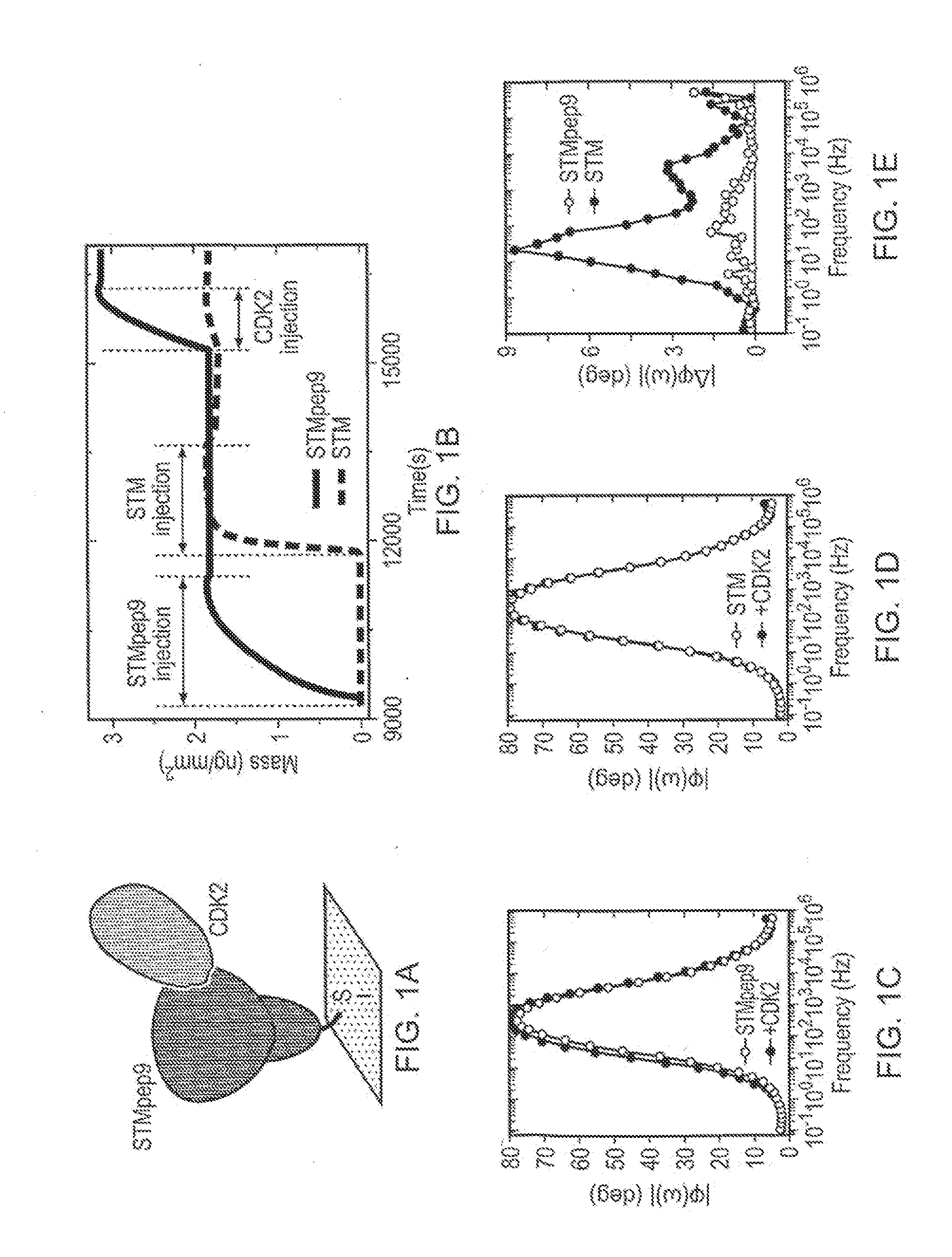
[0166]Two different peptide aptamers were employed displayed by cysteine-modified STM with affinities for cyclin-dependent kinase 2 (CDK2) and CDK4. Both CDK2 and CDK4 belong to a group of proteins involved in the regulation of the cell cycle; they are functionally related, yet share less than 50% sequence identity. The two CDK-interacting peptide aptamers (named STMpep2 and STMpep9, where the subscripts pep2 and pep9 refer to two different peptide sequences) were generated by insertion of oligonucleotides encoding the CDK-interacting peptide sequence derived from the thioredoxin-based peptide aptamers of Colas et al. into restriction sites in the open reading frame encoding the STM protein scaffold. The binding of CDK to the peptide aptamers was confirmed, in vivo and in vitro, using yeast-2-hybrid screening and fluorescence resonant energy transfer spectroscopy (FRET), respectively.

[0167]Although the peptide-insert region is predicted to be far from the surface when the STM-scaffo...

example 2

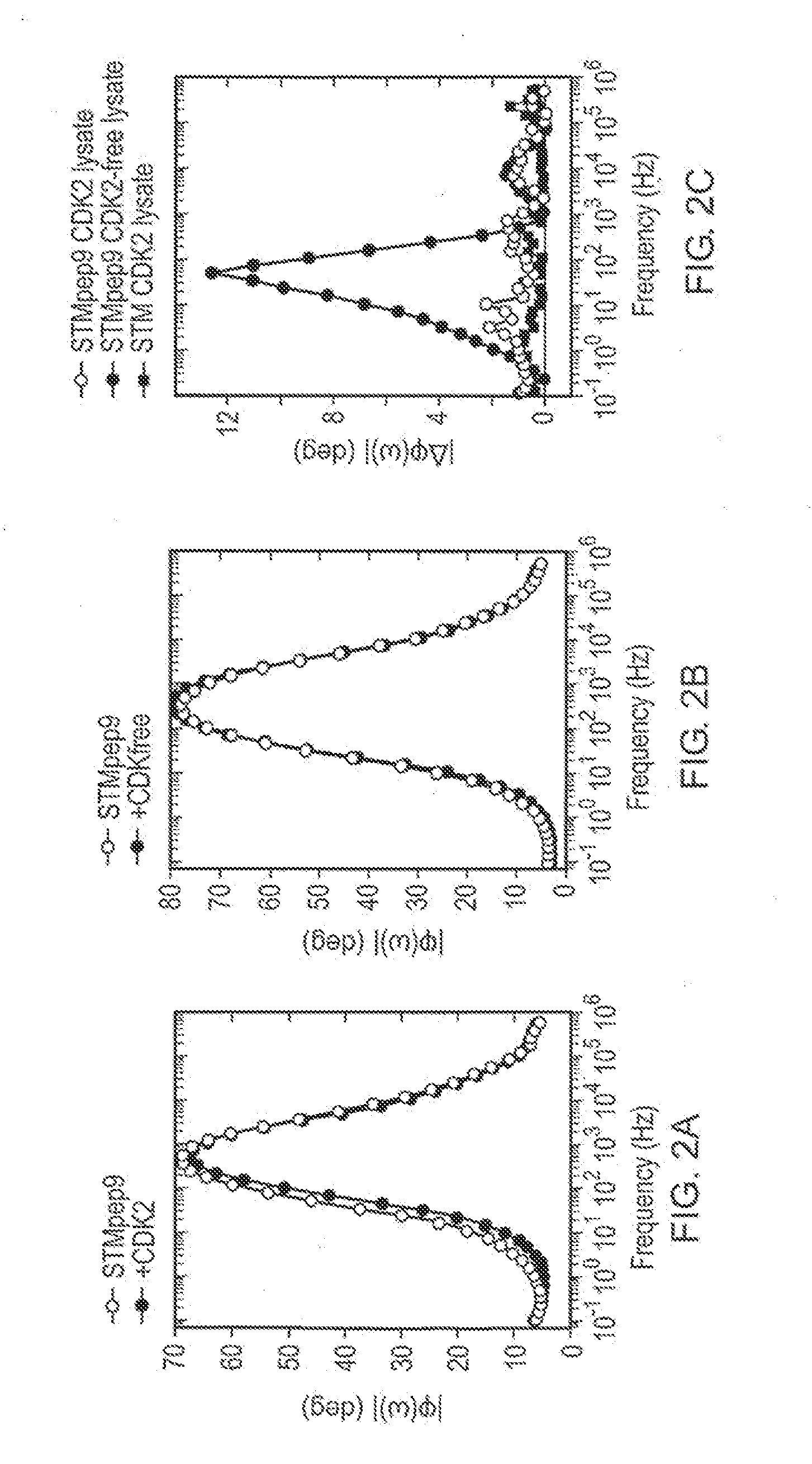
[0174]In order to assess the suitability of our sensing strategy for the detection of proteins in biologically relevant specimens, in which the proteins of interest are only present at very low abundance and in complex mixtures, we prepared Au electrodes functionalised with STMpep9 and STM. These were then exposed to 35 μl of a solution containing a mixture of cell products, including CDK2, generated by lysis (dissolution) of CDK2-expressing yeast cells. The use of a lysate not only allows us to confirm the specificity of the STMpep9 aptamer for binding of CDK2, but also allows us to assess our sensing device using a complex biological sample which closely resembles those used in typical medical diagnostics. Following exposure to yeast lysate, the devices were thoroughly washed in order to remove any non-specifically bound material.

[0175]The phases φ of the complex impedances measured for the different devices are shown in FIG. 2. While a distinct shift in φ(ω) is observed between 1...

example 3

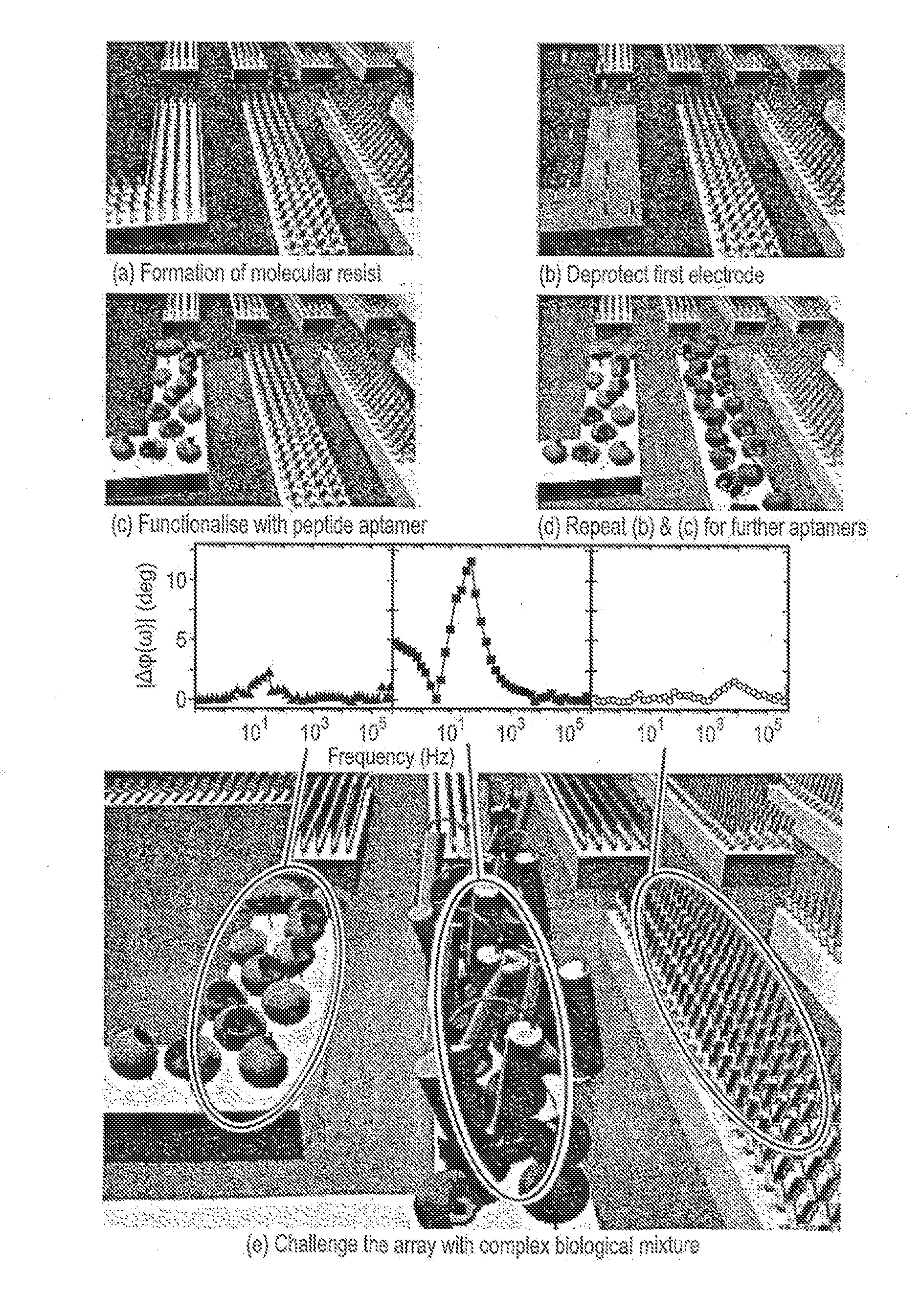
[0176]Electrode array devices consisting of ten individually addressable Au micro-electrodes separated by 15 μm, were fabricated on n-doped silicon substrates capped with a 500 nm thermal oxide using a bi-layer resist process. The electrodes were of 20 μm width. Following fabrication, each device was mounted in a header package and wire bonded to provide electrical connection to each micro-electrode. To demonstrate the suitability of our technique for array format sensing, we functionalised different closely-spaced electrodes of the array with two different peptide aptamers, STMpep9 and STMpep2.

[0177]Selective functionalisation of the micro-electrodes was achieved through a molecular masking process illustrated in FIG. 3. Following the fabrication of the electrode arrays, the devices were immersed in a 10 mM methyl-terminated poly(ethlyene-glycol)6-thiol (mPEG, Polypure, Norway) ethanolic solution for 96 hours (FIG. 3(a)). This mPEG layer prevents non-specific binding of proteins d...


PUM

PropertyMeasurementUnit
diameteraaaaaaaaaa
diameteraaaaaaaaaa
diameteraaaaaaaaaa

Abstract

The invention relates to a method of detecting a structural change in a molecule, said molecule being attached to a surface, said surface being electrically conductive, wherein the phase of the electrochemical impedance at said surface is monitored, and wherein a change in the phase in the electrochemical impedance at said surface indicates a change in the structure of said molecule. The invention further relates to methods for making arrays having molecules such as, polypeptides attached to electrically conductive surfaces such as electrodes, and to arrays.

Description

FIELD OF THE INVENTION [0001]The present invention relates to arrays of biological molecules and their construction. The invention also relates to methods of monitoring structural changes of biological molecules, in particular conformational changes or changes in their molecular association(s).BACKGROUND TO THE INVENTION [0002]High-throughput, high-sensitivity detection or identification of molecules and other nanoscale objects is an important concept not only for medical diagnosis but also for drug-discovery, security, forensic and other applications. The most prominent tools for biological or chemical target detection or identification in a highly parallel fashion are microarrays. In recent years, DNA microarrays have been used extensively in genomic research, where they enabled massively-parallel interrogation of genetic code. However they are only capable of detecting or identifying complementary single stranded DNA or RNA molecules. In cases where other molecules or nanoscale c...

Claims


Application Information

Patent Timeline
Patent Type & Authority Applications(United States)
IPC IPC(8): C40B30/10G01N27/26C40B50/14C40B30/04C40B40/10
CPCB01J19/0046B01J2219/00653G01N33/5438B01J2219/00704B01J2219/00725B01J2219/00659
Inventor KO FERRIGNO, PAULWALTI, CHRISTOPHEVANS, DAVIDJOHNSON, STEVENDAVIES, ALEXANDER GILES
Owner UNIV OF LEEDS
Why Eureka
Try Eureka