Phosphor composite member, LED device and method for manufacturing phosphor composite member

a technology of led devices and composite members, which is applied in the direction of discharge tubes/lamp details, wood working apparatuses, and recording information storage, etc., can solve the problems of long-term stability of white light, difficult to obtain white light, and inability to obtain homogeneous white light sources, etc., to achieve high melting points, reduce luminescence intensity, and high firing temperature

Inactive Publication Date: 2013-02-28
NIPPON ELECTRIC GLASS CO LTD
View PDF7 Cites 28 Cited by
  • Summary
  • Abstract
  • Description
  • Claims
  • Application Information

AI Technical Summary

Benefits of technology

[0014]In the phosphor composite member described in Patent Literature 2, a SiO2—B2O3-based glass is used as the glass powder contained in the sintered glass body layer and a base material containing YAG crystals is used as the ceramic base material. SiO2—B2O3-based glasses generally have high melting points and, therefore, a high firing temperature (for example, 850° C. or more) is required to make a sintered glass body layer from such a glass. Hence, some phosphors u...

Problems solved by technology

However, because the LEDs of the three colors generally have different luminescence outputs, it is difficult to obtain a white light by adjusting the characteristics of the LEDs of the different colors.
Furthermore, even if the LEDs of the three primary colors are collected and arranged in the same plane, a homogeneous white light source cannot be obtained when these LEDs are observed at close range as in an application as a backlight for an LCD, for example.
In addition, because the LEDs of the different colors have different rates of color degradation, there arises a problem with the long-term s...

Method used


Image

  • Phosphor composite member, LED device and method for manufacturing phosphor composite member
  • Phosphor composite member, LED device and method for manufacturing phosphor composite member

Examples


first embodiment

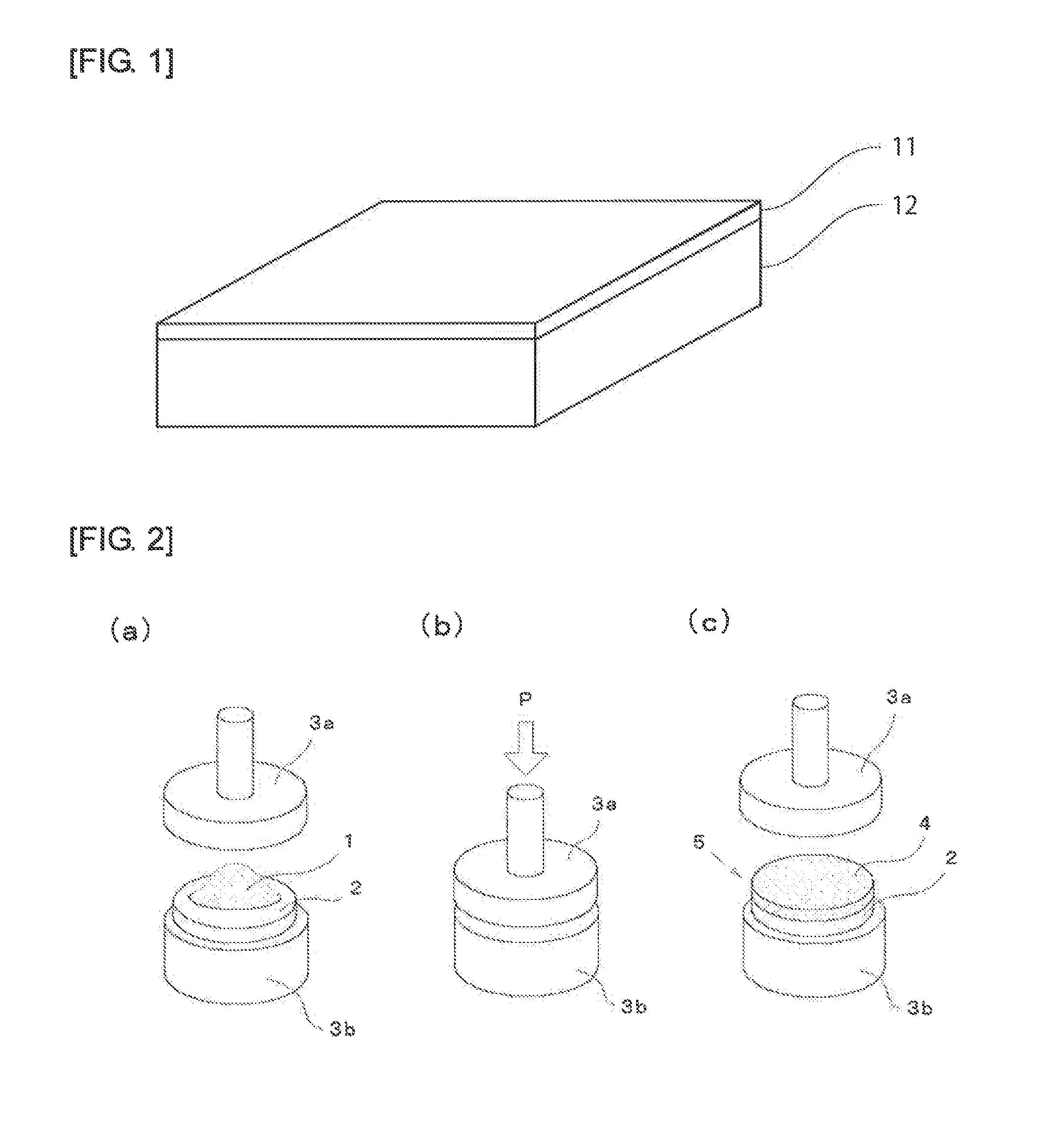
[0061]FIG. 1 shows a schematic view of a phosphor composite member of this embodiment. As shown in FIG. 1, the phosphor composite member of this embodiment is made so that a sintered inorganic powder body layer 11 containing a SnO—P2O5-based glass and an inorganic phosphor powder is formed on a surface of a ceramic base material 12 and is characterized in that upon irradiation with an excitation light, the ceramic base material 12 and the sintered inorganic powder body layer 11 emit different fluorescences having different wavelengths.

[0062]Specifically, in the phosphor composite member of this embodiment, upon irradiation with an excitation light, the ceramic base material 12 preferably absorbs a light in a wavelength range of 400 to 500 nm (preferably a blue light) and emits a fluorescence in a wavelength range of 450 to 780 nm (preferably a yellow fluorescence). On the other hand, the sintered inorganic powder body layer 11 preferably absorbs a light in a wavelength range of 400 ...

example 1

(1) Production of Ceramic Base Material

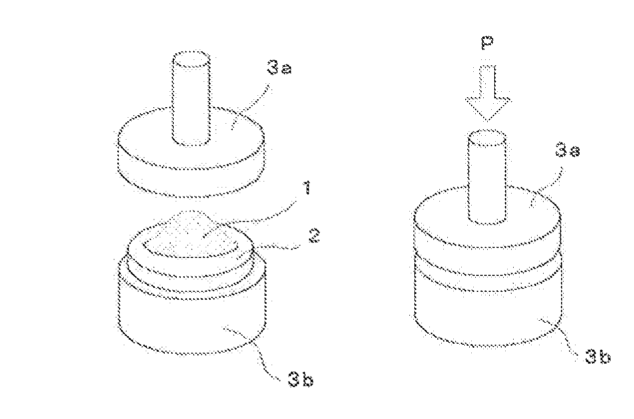
[0123]First, materials having high purity and a particle diameter of 2 μm or less were used, i.e., 37.4625% by mole Y2O3, 62.5% by mole Al2O3, and 0.0375% by mole Ce2O3 were weighed to give a stoichiometric composition of YAG (Y3Al5O12) and 0.6% by mass tetraethoxy silane was added as a sintering additive to these materials. Next, using a ball mil, the prepared materials were mixed with stirring in ethanol for 17 hours, then reduced in pressure, and dried to obtain a powder. Subsequently, the resultant powder was press-molded at a pressure of 200 MPa to make a press molded body having a diameter of 10 mmφ and a thickness of 3 mm, and the press molded body was fired at 1750° C. for 10 hours in a vacuum atmosphere to obtain a fired body. Thereafter, the fired body was polished at both surfaces to have a thickness of 0.1 mm, thereby obtaining a ceramic base material.

[0124]The ceramic base material thus obtained was identified in terms of its preci...

example 2

(1) Production of Green Sheet for Sintered Inorganic Powder Body Layer

[0133]Added to the glass powder produced in Example 1 were SrS:Eu2+ (average particle diameter: 8 μm) and SrBaSiO4:Eu2+ (average particle diameter: 8 μm) as inorganic phosphor powders to give a mass ratio of 94:3:3, followed by mixing to produce a powder mixture. Next added to 100 mass parts of the produced powder mixture were 12 mass parts of polyvinyl butyral resin as a binder, 3 mass parts of dibutyl phthalate as a plasticizer, and 40 mass parts of toluene as a solvent, followed by mixing to produce a slurry. Subsequently, the slurry was formed into a sheet on a PET film by a doctor blade method and then dried to obtain a green sheet having a thickness of 50 μm.

[0134]A sintered inorganic powder body layer produced using the green sheet was measured in terms of luminescence spectra in the same manner as in Example 1. As a result, peaks were observed which were derived from a green fluorescence having a center wa...


PUM

PropertyMeasurementUnit
Temperatureaaaaaaaaaa
Fractionaaaaaaaaaa
Fractionaaaaaaaaaa

Abstract

Provided is a phosphor composite member having excellent thermal resistance, high color rendition, controllability of various chromaticities from a daylight color to a light bulb color, and high luminescence intensity. A phosphor composite member in which a sintered inorganic powder body layer containing a SnO—P2O5-based glass and an inorganic phosphor powder is formed on a surface of a ceramic base material, wherein upon irradiation with an excitation light, the ceramic base material and the sintered inorganic powder body layer emit different fluorescences having different wavelengths.

Description

TECHNICAL FIELD[0001]The present invention relates to a phosphor composite member for emitting a fluorescence by irradiation of an excitation light and providing a white light by synthesis of the excitation light penetrating it and the fluorescence, an LED device, and a method for manufacturing the phosphor composite member.BACKGROUND ART[0002]As a result of development of a blue light emitting diode (LED), a complete set of LEDs covering the three primary colors, RGB (R: red, G: green, and B: blue), of light have been available. Thus, a technique is proposed for producing a white light with the use of these LEDs arranged side by side. However, because the LEDs of the three colors generally have different luminescence outputs, it is difficult to obtain a white light by adjusting the characteristics of the LEDs of the different colors. Furthermore, even if the LEDs of the three primary colors are collected and arranged in the same plane, a homogeneous white light source cannot be obt...

Claims


Application Information

Patent Timeline
IPC IPC(8): B32B17/06B32B37/24B32B33/00H05B33/14B32B18/00
CPCC03C8/08Y10T428/24355C04B41/86C04B41/009C04B41/5022C04B2111/807C03C8/14C04B2237/704C04B2237/58C04B2237/343C04B2235/658C04B2235/6567H01L33/502C09K11/02C09K11/7774C04B35/44C04B2235/3225C04B2235/3229C04B2235/3418C04B2235/441C04B2235/5436C04B2235/764C04B2235/81C04B2235/9646C04B2237/70C04B35/645C04B37/042C04B41/4539C04B41/5027C04B41/5053
Inventor FUJITA, SHUNSUKESUZUKI, RYOTAFURUYAMA, TADAHITO
Owner NIPPON ELECTRIC GLASS CO LTD
Why Eureka
Try Eureka