
Composite drill bit

a drill bit and composite technology, applied in drill bits, earthwork drilling and mining, cutting machines, etc., can solve the problems of difficult teeth to penetrate further into the formation to exert effective crushing, high rock-breaking efficiency, and low energy efficiency of tri-cone bits, etc., to achieve high rock-breaking efficiency, long service life, and high cooling performance

Active Publication Date: 2013-05-23
SOUTHWEST PETROLEUM UNIV
View PDF12 Cites 12 Cited by
  • Summary
  • Abstract
  • Description
  • Claims
  • Application Information

AI Technical Summary

Benefits of technology

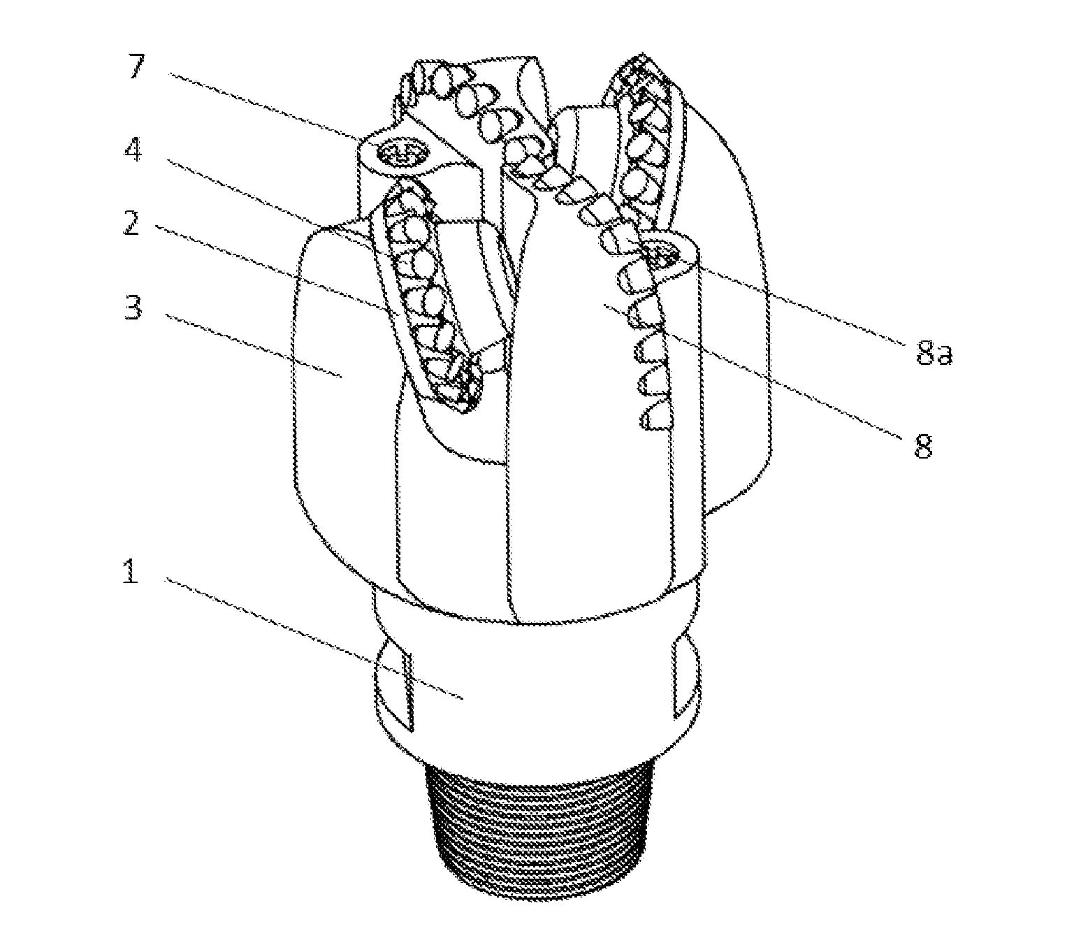
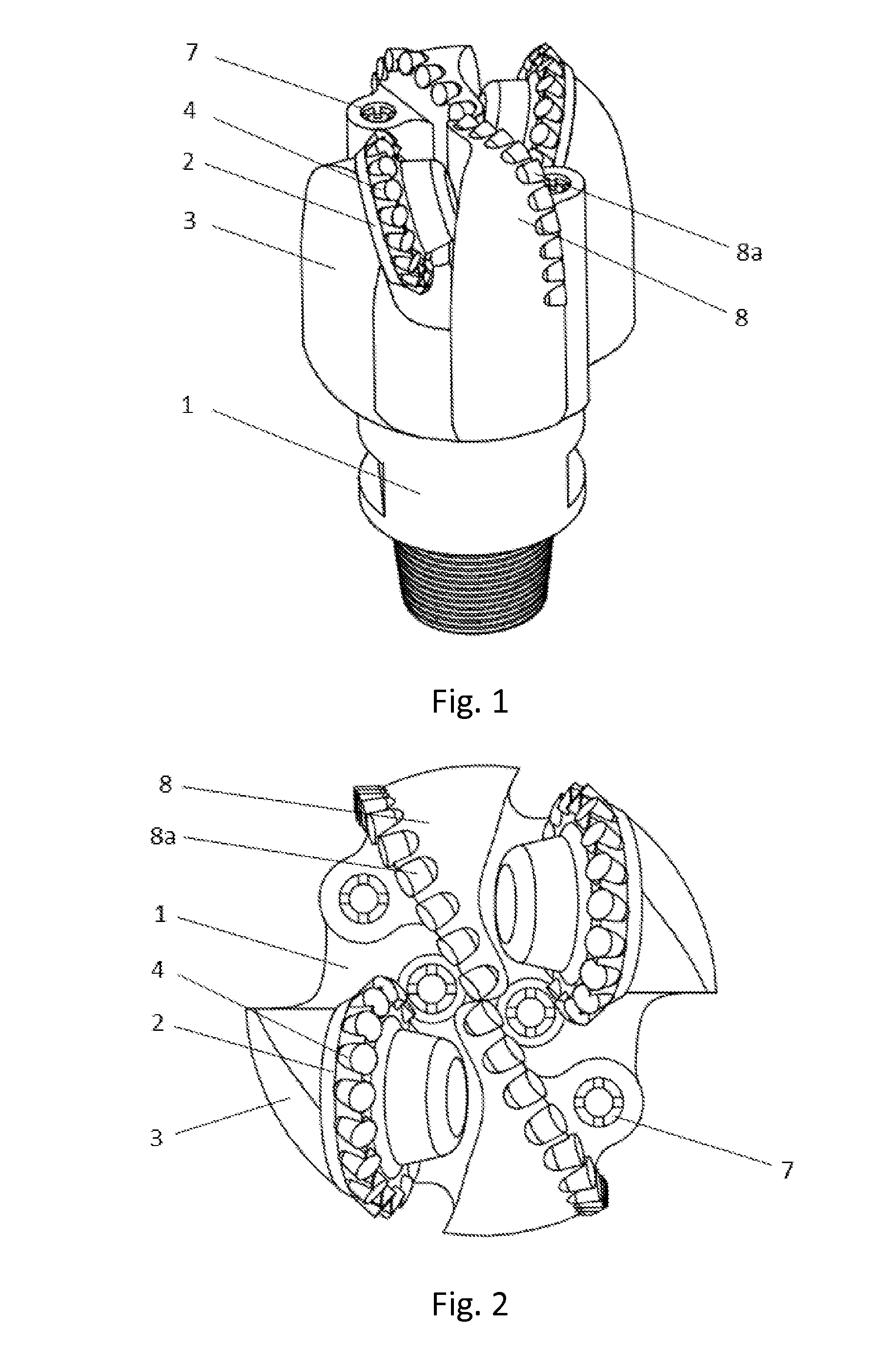
The present invention is a composite drill bit that has a cutting unit with a large angle of deflection and cutters fixed on the bit body. This design allows the scraping-wheel to break rock by scraping it in succession and the cutters on the bit body and the scraping-wheel to cut the bottomhole rock crosswise, creating a mesh-like pattern on the bottomhole, which increases the longevity and rock-breaking efficiency of the drill bit.

Problems solved by technology

Apparently, the compressive strength of rock is much higher than the shear strength and tensile strength, so both energy efficiency and rock-breaking efficiency of the tri-cone bits are relatively low when tri-cone bits break rock by impact crushing.
Especially when drilling in the deep formation, cuttings hold-down effect caused by high density drilling fluid in the bottomhole is very prominent, making it very difficult for the teeth to penetrate further into the formation to exert effective crushing.
One of the main factors limiting the service life of tri-cone bit is the short service life of bearings on it.
Since tri-cone bits break rock by means of impact crushing with a high rotating speed, the bearings suffer large impact and high load amplitude, thus resulting in a short service life for the bearings and accordingly a short life for the bit.
There is, however, one unavoidable weakness for single cone bits, that is, the teeth wear resistance is low, and once the teeth are worn, the rate of penetration (ROP) decreases dramatically.
First, when the PDC cutters continuously cut rock, temperature of the cutters tends to increase to a very high level due to the heat generated by intense friction. When the temperature exceeds a certain level, the wear rate of PDC cutters will increase significantly, causing thermo-wear effect (i.e., when the working temperature of a PDC cutter exceeds a certain level, wear resistance of the cutter decreases significantly) to happen.
Second, the failure of individual cutter (dropping-off, breaking or excessive wearing, etc.) will significantly increase the cutting load of those cutters located adjacent to it, thus accelerating the wear of the cutters, and consequently causing premature failure of the drill bit.
Third, the wear rate of bit cutters located in different radial areas is uneven, typically, much higher in the outer area (especially in the outer ⅓ radial area) than in the central area.

Method used


Image

  • Composite drill bit
  • Composite drill bit
  • Composite drill bit

Examples


embodiment 1

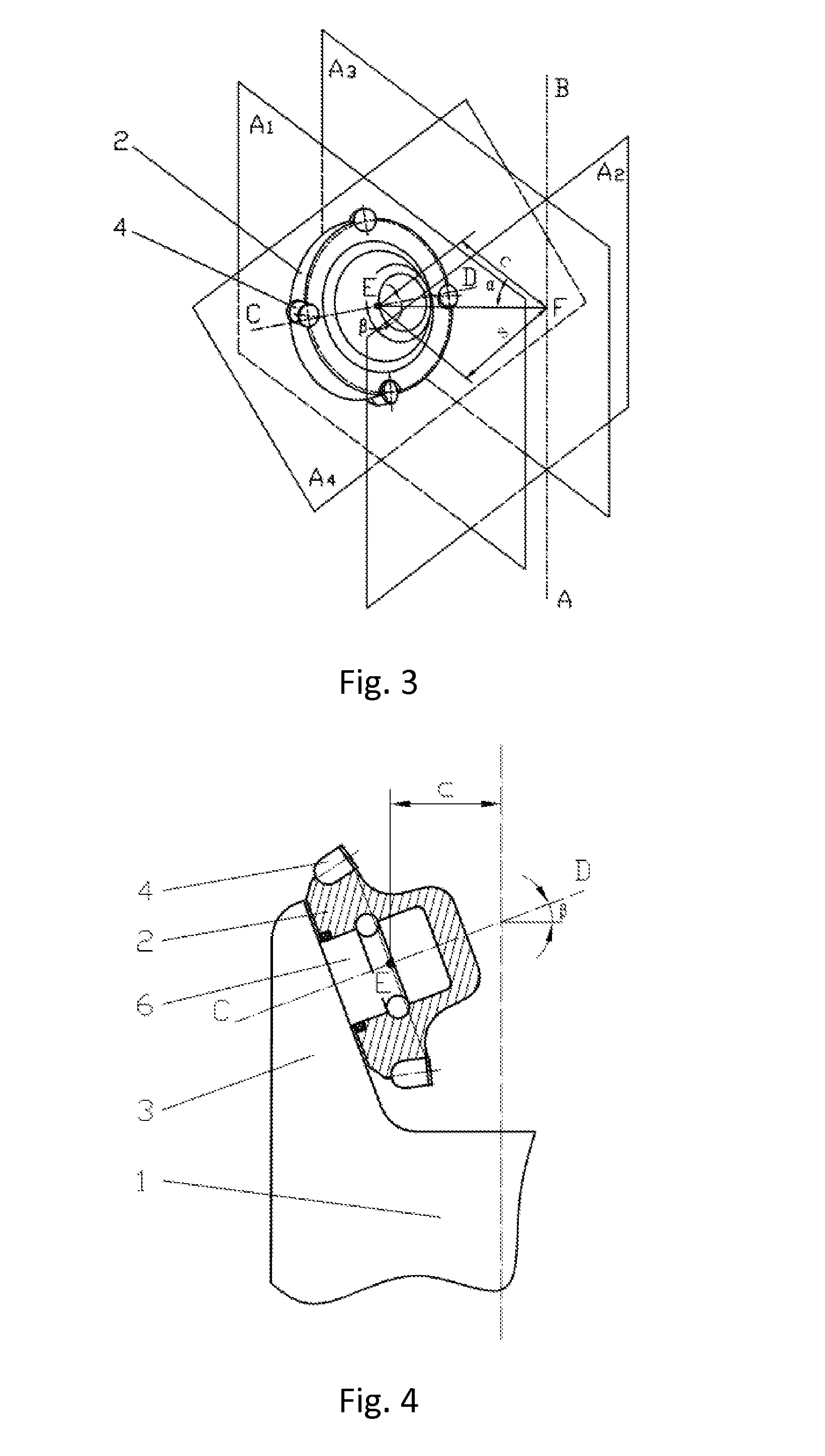
[0083]When the scraping-wheel (2) angular deflection α=±20°, take as example a drill bit with the external diameter (take the farthest point from the drill bit axis on the scraping-wheel as the gage point) D=8.5 inch (215.9 mm). Take the scraping-wheel (2) outer-row (4) radius r=65 mm, scraping-wheel journal angle β=0°, since:

s=c·tanα(1)(D2)2=(r+s)2+c2(2)

[0084]From equations (1) and (2), it can be obtained that the reference distance c=62.75 mm, scraping-wheel (2) offset distance s=22.84 mm.

[0085]With the above parameters, the radial slippage distance of the cutters on the outer-row (4), from entering to exiting from the bottomhole rock, will be 41.17 mm. According to both theoretical calculation and experiments conducted, the wheel / bit rotational speed ratio under such condition is below 0.96, i.e. the self-rotation speed of the scraping-wheel (2) is low when drilling, thus cutters on the scraping-wheel (2) penetrate into the formation with a slow speed, scraping a relatively long ...

embodiment 2

[0088]When the scraping-wheel (2) angular deflection α=±30°, still take a drill bit with external diameter D=215.9 mm as example. Take the scraping-wheel outer-row (4) radius r=65 mm.

[0089]According to equations (1) and (2), reference distance c=51.62 mm, scraping-wheel (2) offset s=29.81 mm.

[0090]With the above parameters, the cutters radial slippage will be 48.34 mm. According to both theoretical calculation and experiments conducted, the wheel / bit rotational speed ratio under such condition is below 0.79, that is, it can be achieved for the cutters on the scraping-wheel (2) to successively scrap the bottomhole rock with a low speed. FIG. 12, with the angular deflection of the drill bit α=30°, shows the mesh-like scraping pattern created by an embodiment of the present invention with a combination of scraping-wheel cutting units and fixed cutting units. As illustrated in the Figure, the slippage of the scraping-wheel is longer than when α=±20°, showing the successive scraping char...

embodiment 3

[0091]When the scraping-wheel (2) angular deflection α=±40°, D and r take the same values as above, according to equations (1) and (2), c=41.37 mm, s=34.71 mm.

[0092]With the above parameters, the cutters radial slippage will be 53.95 mm, and wheel / bit rotational speed ratio is below 0.64. FIG. 13, with the angular deflection of the drill bit α=40°, shows the mesh-like scraping pattern created by an embodiment of the present invention with a combination of scraping-wheel cutting units and fixed cutting units. Apparently in the Figure, the slippage of the cutters on the scraping-wheel is longer than when α=±30°.


PUM


Abstract

A composite drill bit with a bit body configured at its upper extend for connection into a drillstring, comprising: a bit body (1) with at least one bit leg (3), at least one scraping-wheel (2) set with a cutter-row (4), and a set of cutters fixed thereon. The scraping-wheel (2) is mounted for rotation on the corresponding bit leg (3) with a large angular deflection α in the range of 20°≦|α|≦90°. The cutters on the scraping-wheel break rock by means of successive scraping, forming a cross-cutting area on the bottomhole accompanied by the cutters on the fixed cutting unit, thus achieving high rock-breaking efficiency, even wear, high cooling performance, and a longer service life for the cutters, bearings and the drill bit.

Description

TECHNICAL FIELD[0001]The present disclosure is related to drilling equipment technologies in petroleum and natural gas, mining engineering, infrastructure construction, geological and hydrological projects. More particularly, it is related to a composite drill bit.DESCRIPTION OF THE RELATED ART[0002]Drill bit is a rock-breaking tool in drilling engineering used to break rock and to form wellbores. Currently, drill bits used in drilling engineering are mainly cone bits (typically tri-cone bits and single cone bits) and PDC (polycrystalline diamond compact) bits.[0003]As for the tri-cone bits, they break rock mainly by means of crushing, the cone / bit rotational speed ratio (the rotating speed ratio between the cone and the bit body in the drilling process) of tri-cone bits is larger than 1, so that the cone rotates fast with the teeth on it getting a short time contacting the formation, thus teeth exert impact crushing to break the bottomhole rock. Apparently, the compressive strength...

Claims


Application Information

Patent Timeline
IPC IPC(8): E21B10/08E21B10/50
CPCE21B10/14E21B10/20E21B10/16E21B10/50
Inventor YANG, YING XINCHEN, LIANLIN, MINPEI, ZHUREN, HAI TAO
Owner SOUTHWEST PETROLEUM UNIV
Learn More