
Regenerable solvent mixtures for acid-gas separation

a solvent mixture and acid-gas technology, applied in the field of solvent systems, can solve the problems of contributing to the cost of purified products, the cost of purified acid-gas has become a significant hurdle, and the performance of flue gas is not good in the humid, near-ambient pressure conditions

Active Publication Date: 2013-06-27
RES TRIANGLE INST
View PDF1 Cites 7 Cited by
  • Summary
  • Abstract
  • Description
  • Claims
  • Application Information

AI Technical Summary

Benefits of technology

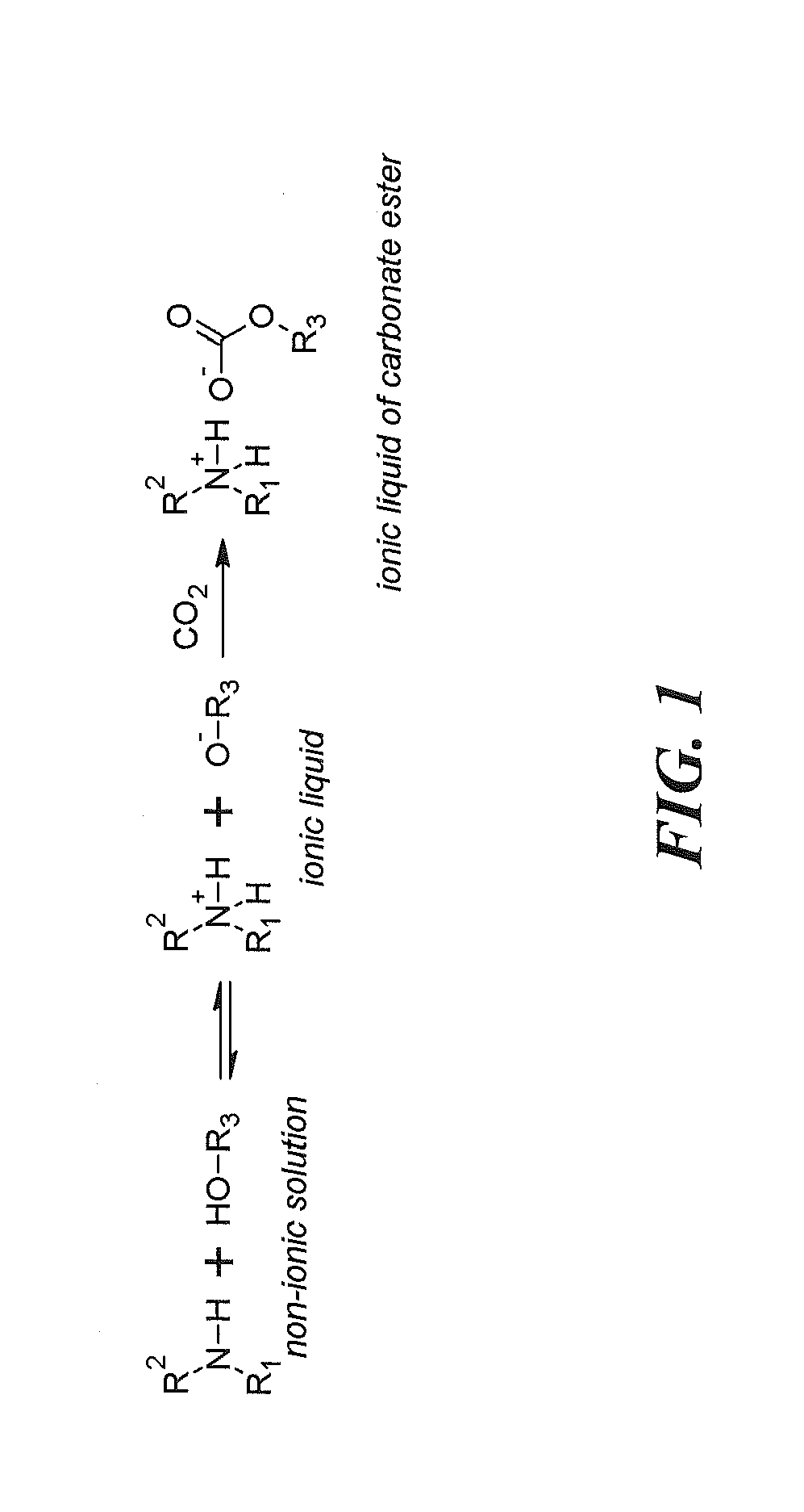
The present invention relates to a solvent system for removing acid gas components from a gas stream. The solvent system comprises an ionic liquid formed from the conjugate base of an acidic component and the conjugate acid of a nitrogenous base. The solvent system can absorb acid gas components from the gas stream to form a carbonate ester or a heteroatom analogue of a carbonate ester. The solvent system has a high conductivity and is immiscible with water. The invention also includes a method for removing acid gas components from a gas stream by contacting it with the solvent system. The technical effects of the invention include efficient removal of acid gas components from gas streams and the formation of a high-density solvent.

Problems solved by technology

The energy required to obtain purified acid-gas from the rich solvent contributes to the cost of the purified product.
In particular, the cost of the purified acid-gas has become a significant hurdle for the application of solvent technologies to fossil-fuel fired power plants for the removal of acid gases from flue gas.
Single-component alcoholic physisorption solvents such as RECTISOL™ and SELEXOL® are commercially available for CO2 separation but perform poorly in the humid, near-ambient pressure conditions associated with flue gas.
They have low regeneration requirements but have not surpassed aqueous amine solvents in performance due to factors including CO2 loading capacity, viscosity, cost, and, importantly, degradation by water.
H2O accumulation is detrimental to the CO2 separation and purification process, since more energy will be required for solvent regeneration due to the necessity of continually removing water from the solvent.
While these solvents are a promising alternative technology, those that have been previously disclosed are poorly suited for flue gas applications due to their chemistries with respect to water, which typically is a major component of flue gas.

Method used


Image

  • Regenerable solvent mixtures for acid-gas separation
  • Regenerable solvent mixtures for acid-gas separation
  • Regenerable solvent mixtures for acid-gas separation

Examples


example 1

Absorption of CO2 by 1,1,3,3-tetramethylguanidine / 2,2,2-trifluoroethanol resulting in formation of a carbonate ester.

[0056]An equimolar solution of 1,1,3,3-tetramethylguanidine (“TMG”) and 2,2,2-trifluoroethanol (“TFE”) was prepared, resulting in an exothermic event with moderate generation of heat. The solution was placed in an impinger and purged with a binary gas mixture containing approximately 13% CO2 (balance nitrogen). The CO2 concentration of the gas exiting the reactor was monitored by an NDIR CO2 analyzer. The CO2 loading curve is shown in FIG. 7. Upon heating the solution to 80° C. in a flowing stream of nitrogen, the absorption was reversed, resulting in the release of approximately 0.56 moles CO2 / mole amine.

[0057]FIG. 8 provides a nuclear magnetic resonance (NMR) spectrum of the result of the reaction between the TMG / TFE solvent system and gaseous CO2. In an NMR tube at room temperature, 1,1,3,3-tetramethylguanidine (0.6 mmol) was combined with 2,2,2-trifluoroethanol (0...

example 2

Absorption of CO2 by an ionic liquid consisting of an equimolar mixture of 1,1,3,3-tetramethylguanidine and 1,1,3,3-tetrafluoropropanol

[0060]1,1,3,3-tetramethylguanidine was combined with an equimolar amount of 2,2,3,3-tetrafluoropropanol, giving an exothermic reaction occurs resulting in formation of a room temperature ionic liquid, with initial conductivity equal to approximately 440 μS / cm2, as shown in FIG. 9. This figure further shows that, when the ionic liquid was purged with a binary gas mixture composed of approximately 13.3% CO2 (balance nitrogen), the conductivity of the solution increased to a maximum of approximately 1175 μS / cm2. This data (an increase in conductivity) corresponds to the absorption of CO2 by the solution as evidenced by the observed decrease in the concentration of the gas passing through the solution as followed with a CO2 analyzer utilizing NDIR spectroscopy. The solution absorbed approximately 0.35 moles CO2 / mole of amine. When heated to approximately...

example 3

Absorption of CO2 by an ionic liquid consisting of an equimolar mixture of 1,1,3,3-tetramethylguanidine and 2,2,3,3,4,4,-hexafluorobutanol

[0061]An equimolar mixture of 1,1,3,3-tetramethylguanidine with 2,2,3,3,4,4-hexafluorobutanol formed a room temperature ionic liquid is formed, with initial conductivity equal to approximately 400 μS / cm2 as shown in FIG. 10. As further shown in this figure, when the ionic liquid was purged with a binary gas mixture composed approximately 13.3% CO2 (balance nitrogen) the conductivity of the solution increased to a maximum of approximately 800 μS / cm−1. This data (an increase in conductivity) shows that the solution absorbs CO2 as evidenced by the observed decrease in the concentration of the gas passing through the solution as followed with a CO2 analyzer utilizing NDIR spectroscopy. This indicates that the lean solvent is an ionic liquid whose conductivity increases with absorption of carbon dioxide. The solution absorbed a total of approximately 0...


PUM

PropertyMeasurementUnit
pKaaaaaaaaaaa
molar ratioaaaaaaaaaa

Abstract

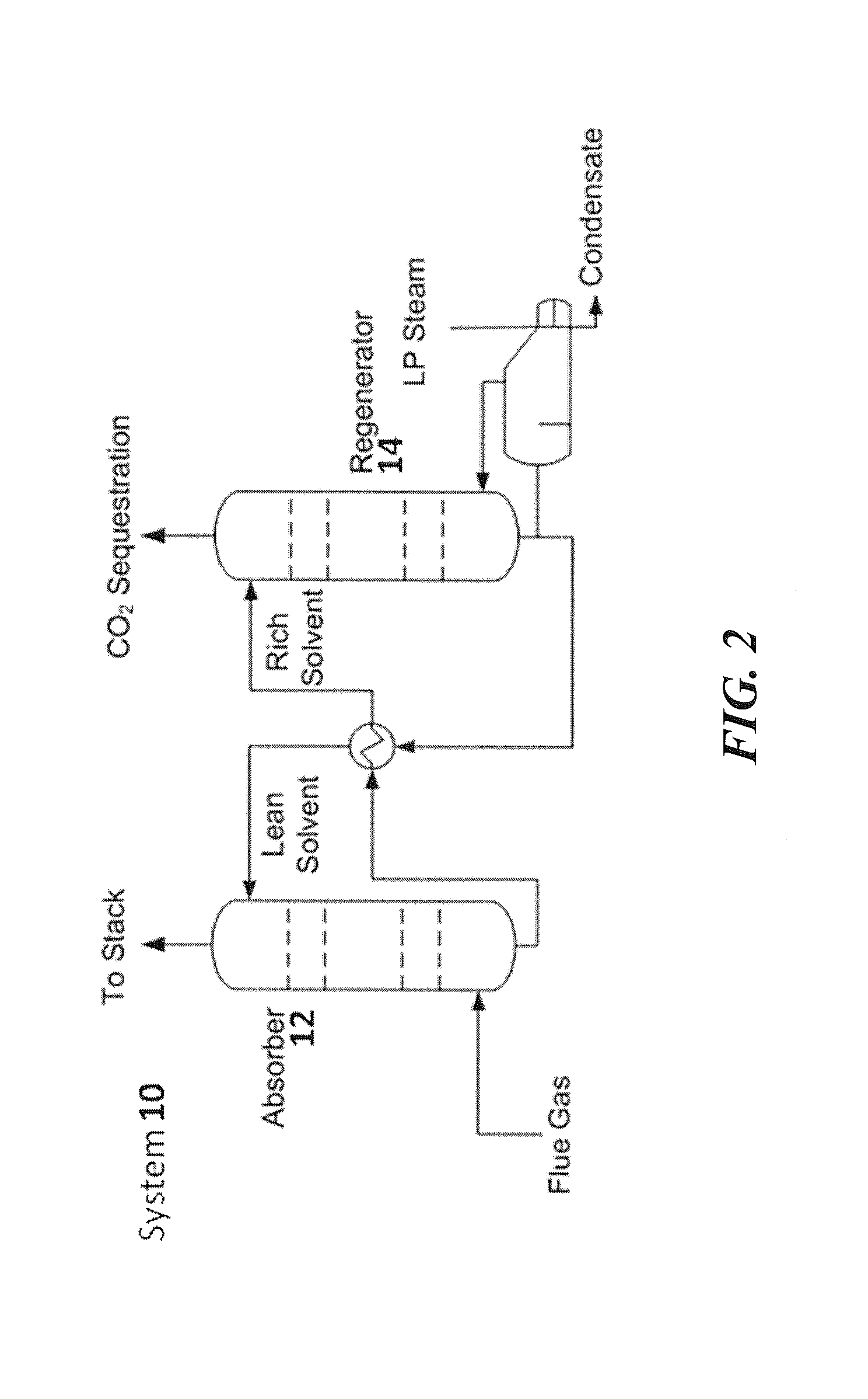
A solvent system comprising an ionic Liquid formed from a relatively acidic component and a nitrogenous base for the removal of acid gases from mixed gas streams is provided. Also provided is a process for removing acid gases from mixed gas streams using the disclosed solvent system. The solvent system may be utilized within a gas processing system.

Description

FIELD OF THE INVENTION[0001]The present invention relates to solvent systems for the removal of specific components of gas streams, as well as devices and methods using such systems. More specifically, the invention can provide for removal of acid gases, such as CO2, SO2, COS, CS2 and NOx. The invention further can provide for continuous operation of devices and methods using the system. Further, the inventive methods can utilize multiple absorption / desorption means, including gas absorption / desorption or phase-enhanced absorption / desorption.BACKGROUND OF THE INVENTION[0002]Various strategies are being pursued to minimize the production and / or release of undesirable emissions from combustion processes. One such strategy is the development of technologies for the specific removal of acid gases from gas mixtures, such as the exhausts of carbon combustion processes. The separation of acid gases, such as CO2, from gas mixtures has been carried out industrially for over a hundred years, ...

Claims


Application Information

Patent Timeline
Patent Type & Authority Applications(United States)
IPC IPC(8): B01D53/40
CPCB01D53/1425Y02C10/06B01D53/1475B01D53/1493B01D2252/202B01D2252/20405B01D2252/20421B01D2252/20426B01D2252/504B01D2257/30B01D2257/302B01D2257/308B01D2257/404B01D2257/504B01D2258/0283B01D53/40B01D53/1456Y02C20/40Y02A50/20
Inventor LAIL, MARTYCOLEMAN, LUKE
Owner RES TRIANGLE INST
Learn More