
Real time equivalent model, device and apparatus for control of master oscillator power amplifier laser

a power amplifier and real-time equivalent technology, applied in the field of lasers, can solve the problems of lasers still limited to the operating points contained in the laser, poor solution of the lookup table, and catastrophic optical damage to the amplifier

Active Publication Date: 2013-07-11
KONGSBERG MARITIME
View PDF3 Cites 32 Cited by
  • Summary
  • Abstract
  • Description
  • Claims
  • Application Information

AI Technical Summary

Benefits of technology

The present invention allows pulsed lasers to operate at low frequencies and control pulse trains. It also provides a device to easily measure and control parameters of the amplifier. Furthermore, it eliminates the need for a laborious lookup table to control laser pulse energy.

Problems solved by technology

For MOPA lasers to operate at low pulse repetition frequency, pump control is required as the equilibrium would be at stimulated and spontaneous deexcitation levels which would either cause spontaneous lasing or peak power levels causing catastrophic optical damages to the amplifier.
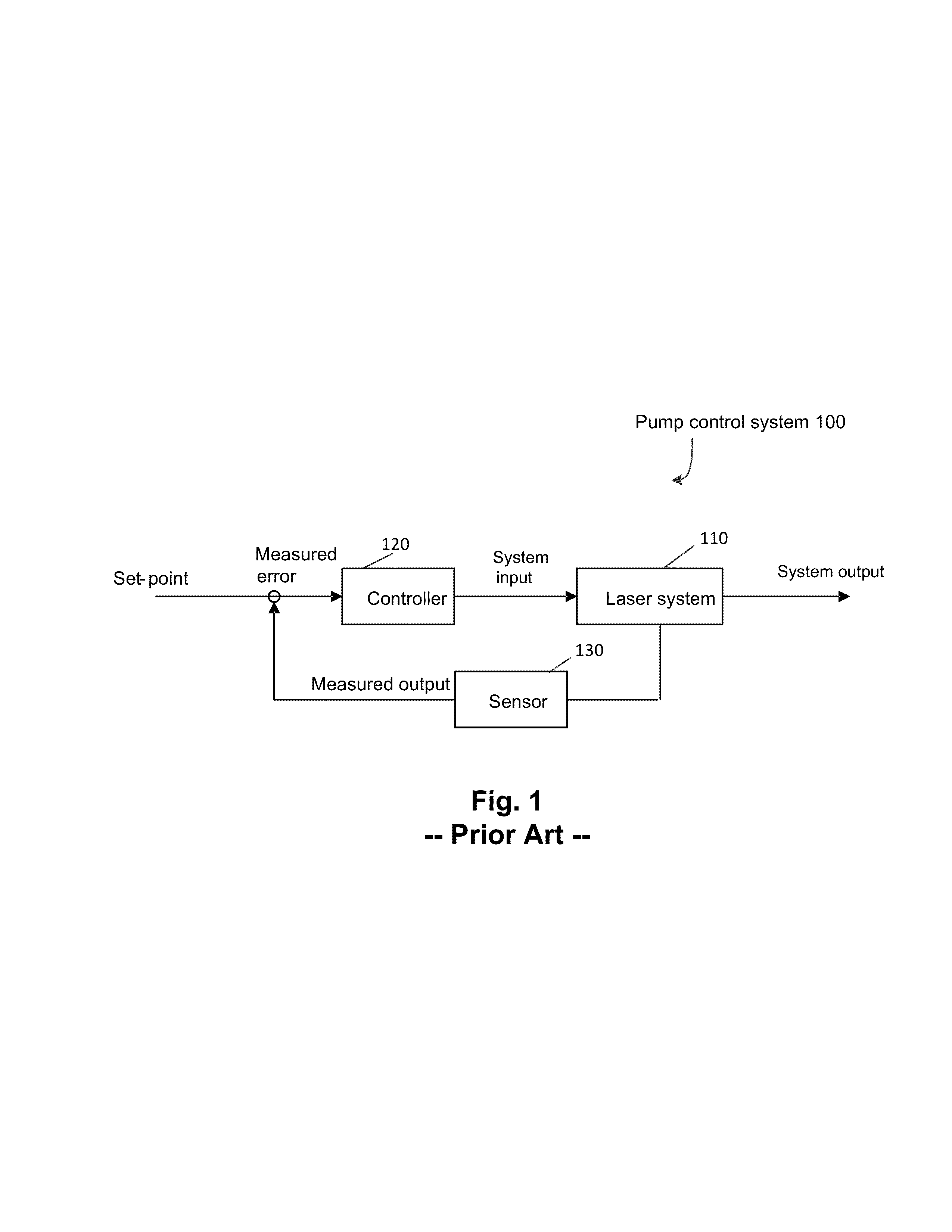
However, the lookup table is a poor solution, since the process of creating it is time consuming, laborious, and difficult.
Also, the laser is still limited to the operating points contained in the lookup table.
Furthermore, the lookup needs to happen in real time, placing demanding requirements on the electronics and inevitably forcing a compromise between timing and accuracy.
However, limiting the operating frequency range to only high frequency limits the number of applications in which the laser can be used.
For example, the maximum measurable distance in a light detection and ranging (LIDAR) system can be limited by pulse ambiguity if low frequency pulses are not used.
A drawback of utilizing such a feedback technique is that it relies on optical measurement of the magnitude of fluorescence from the gain medium.
However, in this case, the fluorescence detection device needs to tolerate the high pump or signal power also present at those locations.
Even with optical filters, a system with sufficient power handling will generally lack the resolution necessary to accurately estimate the error in laser inversion.
This is due to the limitations in dynamic range of converting intensity in the optical domain to voltage in the electrical domain.
Moreover, the magnitude of fluorescence at some points is not an accurate measurement of the effective population inversion in the gain medium.
These drawbacks with prior known approaches lead to a cumbersome system and poor control of the of the gain medium and hence output energy.

Method used


Image

  • Real time equivalent model, device and apparatus for control of master oscillator power amplifier laser
  • Real time equivalent model, device and apparatus for control of master oscillator power amplifier laser
  • Real time equivalent model, device and apparatus for control of master oscillator power amplifier laser

Examples


Embodiment Construction

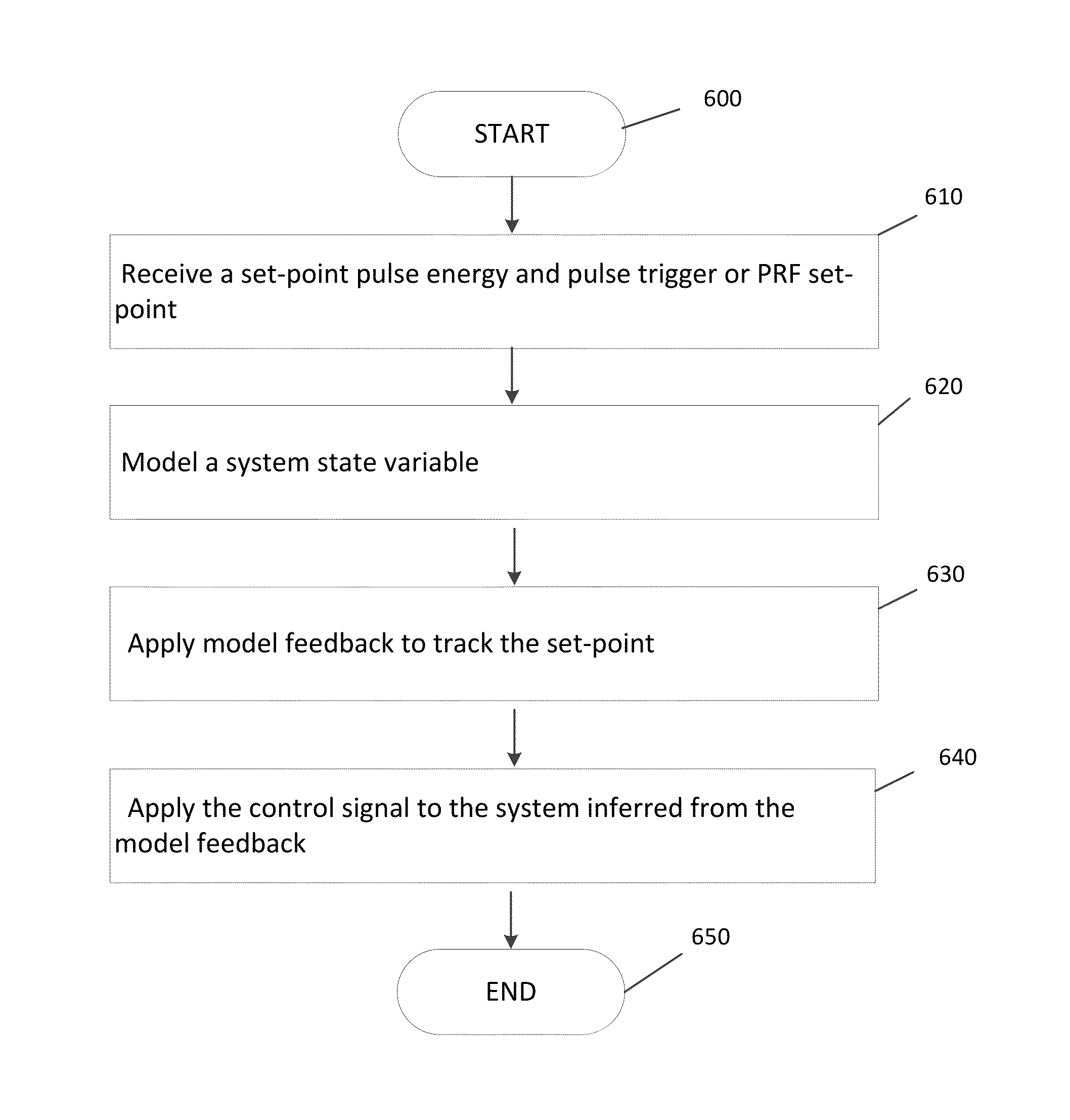
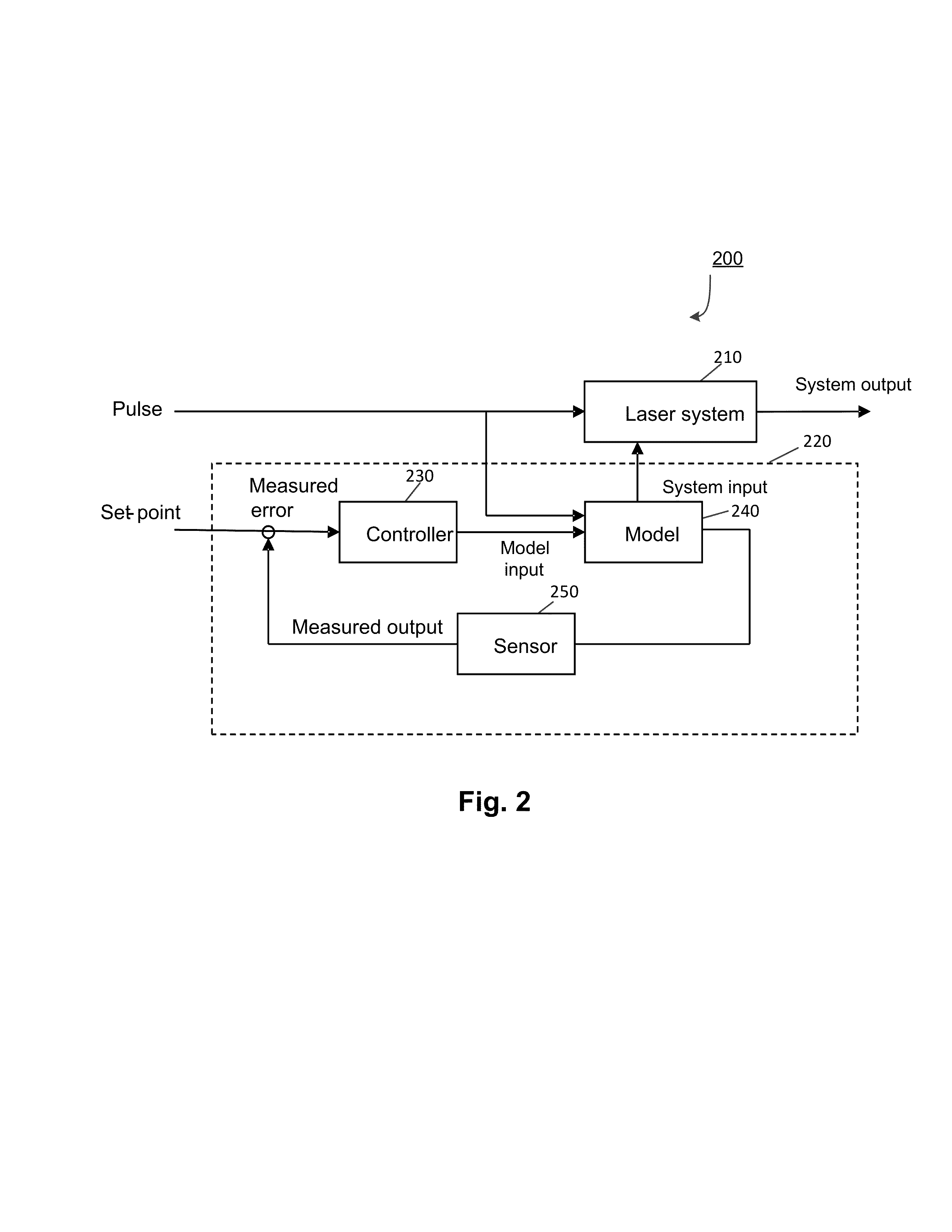
[0025]Further features and advantages of the invention, as well as the structure and operation of various embodiments of the invention, are described in detail below with reference to the accompanying FIGS. 2-6, wherein like reference numerals refer to like elements. Although the invention is described in the context of fiber amplifiers and fiber lasers, one of ordinary skill in the art appreciates that the control techniques disclosed herein can be applied to any system in which a state variable can be estimated in real time such that the model state variable can be controlled by a closed loop feedback. The system control signal is inferred from the model closed loop signal. In particular, the invention applies to different types of pulsed laser such as, but not limited to Q-switched lasers, solid state bulk lasers, microchip lasers, excimer lasers, mode-locked lasers, gain-switched semiconductor lasers, and cavity-dumped lasers.

[0026]The present invention provides, among other thi...


PUM


Abstract

The present invention provides, in at least one embodiment, a system and method for power control of lasers. The system includes a device's control signal fed into a laser. The laser can be a master oscillator power amplifier (MOPA) fiber laser. The device includes an equivalent model circuit representing at least one parameter of the laser, such as the gain fiber inversion in the power amplifier. The device measures the power at the equivalent model circuit. Then, the device uses its feedback signal to control and / or adjust the output power control signal fed into the laser based on the measured power. By controlling the power fed into the laser, the laser can be operated at much lower frequencies while keeping the laser power within acceptable limits.

Description

BACKGROUND OF THE INVENTION[0001]1. Field of Invention[0002]The invention relates generally to lasers and more particularly, to techniques for controlling amplifier power in master oscillator power amplifier (MOPA) fiber lasers.[0003]2. Description of Related Art[0004]Pulsed lasers are lasers which emit light not in a continuous mode, but rather in the form of optical pulses. Depending on the pulse duration, pulse energy, pulse repetition rate and wavelength required, different methods for pulse generation and types of pulse lasers may be used. For example, various types of Q-switched lasers can be used to generate nanosecond pulse durations. High pulse energies are achievable with solid-state bulk lasers. For smaller pulse energies, a microchip laser or a fiber laser can be suitable. For boosting the average power (particularly of high repetition rate pulse trains with moderate pulse energies), high-power fiber amplifiers can be used.[0005]Power scaling of a laser is increasing its...

Claims


Application Information

Patent Timeline
IPC IPC(8): H01S3/10
CPCH01S3/06754H01S3/1305H01S3/1306H01S3/10069H01S3/1618
Inventor BERENDT, MARTIN
Owner KONGSBERG MARITIME
Learn More