Eureka AIR delivers breakthrough ideas for toughest innovation challenges, trusted by R&D personnel around the world.

Improved Heat Utilization In ORC Systems

a heat utilization and orc technology, applied in the direction of machines/engines, waste based fuel, energy input, etc., can solve the problems of unavoidable significant unwanted heat generation, unavoidable degree of residual heat escape or remain, and achieve the effect of managing and/or dispersing the degree of residual hea

Active Publication Date: 2013-08-08
BITZER US
View PDF9 Cites 22 Cited by
  • Summary
  • Abstract
  • Description
  • Claims
  • Application Information

AI Technical Summary

Benefits of technology

The patent text describes how a biogas generation system can be combined with a prime mover and an ORC system to efficiently generate power and fuel. The biogas can be used as fuel for the prime mover, and the system can operate using waste heat from the prime mover to drive the biogas generation system. This combined system can provide simultaneous power to a wide variety of devices and applications. The system can also use heat from the ORC system to optimize the production of biogas, which can improve the efficiency and cost-effectiveness of the combined system. The use of an ORC system can also eliminate the need for a separate anaerobic digestion tank heating system, reducing costs and environmental impact. Overall, the technology allows for a more economical, physical, and environmentally beneficial combination of a biogas generation system with a prime mover and an ORC system.

Problems solved by technology

While the creation of heat energy may be the desired outcome of such a process, as with a boiler installed to provide radiant heat to a building using a network of conduits which circulate hot water to radiators or a furnace used for the smelting of metals, in many other instances unwanted heat is produced as a byproduct of the primary process.
One such example is that of the internal combustion ermine of an automobile where the primary function is to provide motive force but where the generation of significant unwanted heat is unavoidable.
Even in those processes where the generation of heat energy is desired, some degree of residual heat unavoidably escapes or remains which can be managed and / or dissipated.
This wasted enemy detracts from the performance, efficiency, and cost effectiveness of the system.
With respect to the internal combustion engine common to most automobiles, considerable waste heat energy is generated by the combustion of fuel and the friction of moving parts within the engine.
In operation, these engines generate tremendous amounts of waste heat energy that has historically been dissipated into the environment.
Unless recaptured and repurposed, however, the portion of the input energy converted to heat is lost.
In many prior art systems, this heat energy is lost and additional energy is required to cool the recirculating jacket water.
The heat from exhaust gas generally escapes into the atmosphere, and the recirculating jacket water is cooled by an outboard apparatus (such as by large external condensing radiators driven by forced air sources), which consume additional electric power to function and further reduce the efficiency of the system.
Additionally, the dissipation of this waste heat energy into the environment can have deleterious effects.
Localized heating may adversely affect local fauna and flora and can require additional power, either generated locally or purchased commercially, to provide additional or specialized cooling.
Further, the noise generated by forced air cooling of the jacket water heat radiators can have undesirable secondary effects.
These systems consume considerable energy and therefore have an attendant cost of operation and maintenance.
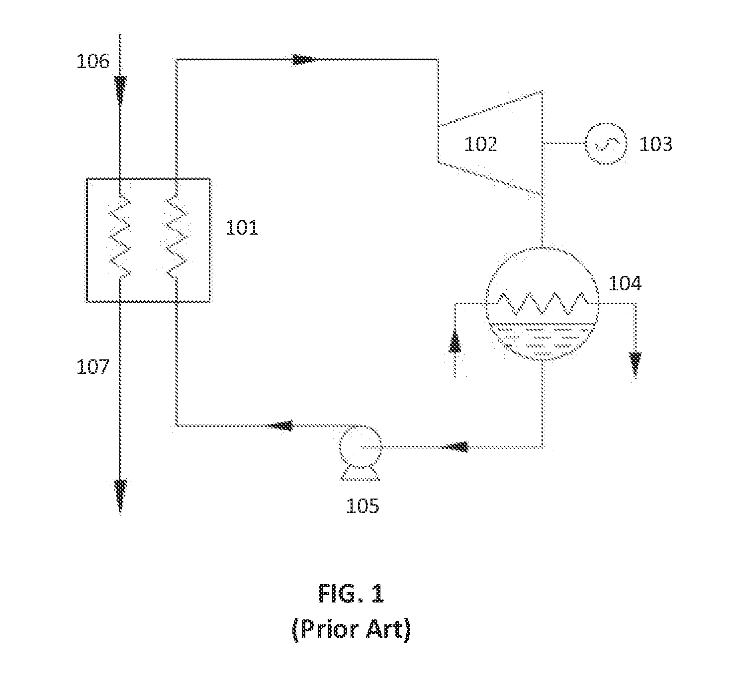
ORC systems can extract as much useful heat energy as is practicable from one or more waste heat sources (often referred to as the “prime mover”), but owing to various physical limitations they cannot convert all available waste heat to mechanical or electric power via the expansion process discussed above.
The heat energy lost in this condensation process, however, represents wasted energy which detracts from the overall efficiency of the system.

Method used


Image

  • Improved Heat Utilization In ORC Systems
  • Improved Heat Utilization In ORC Systems
  • Improved Heat Utilization In ORC Systems

Examples


Embodiment Construction

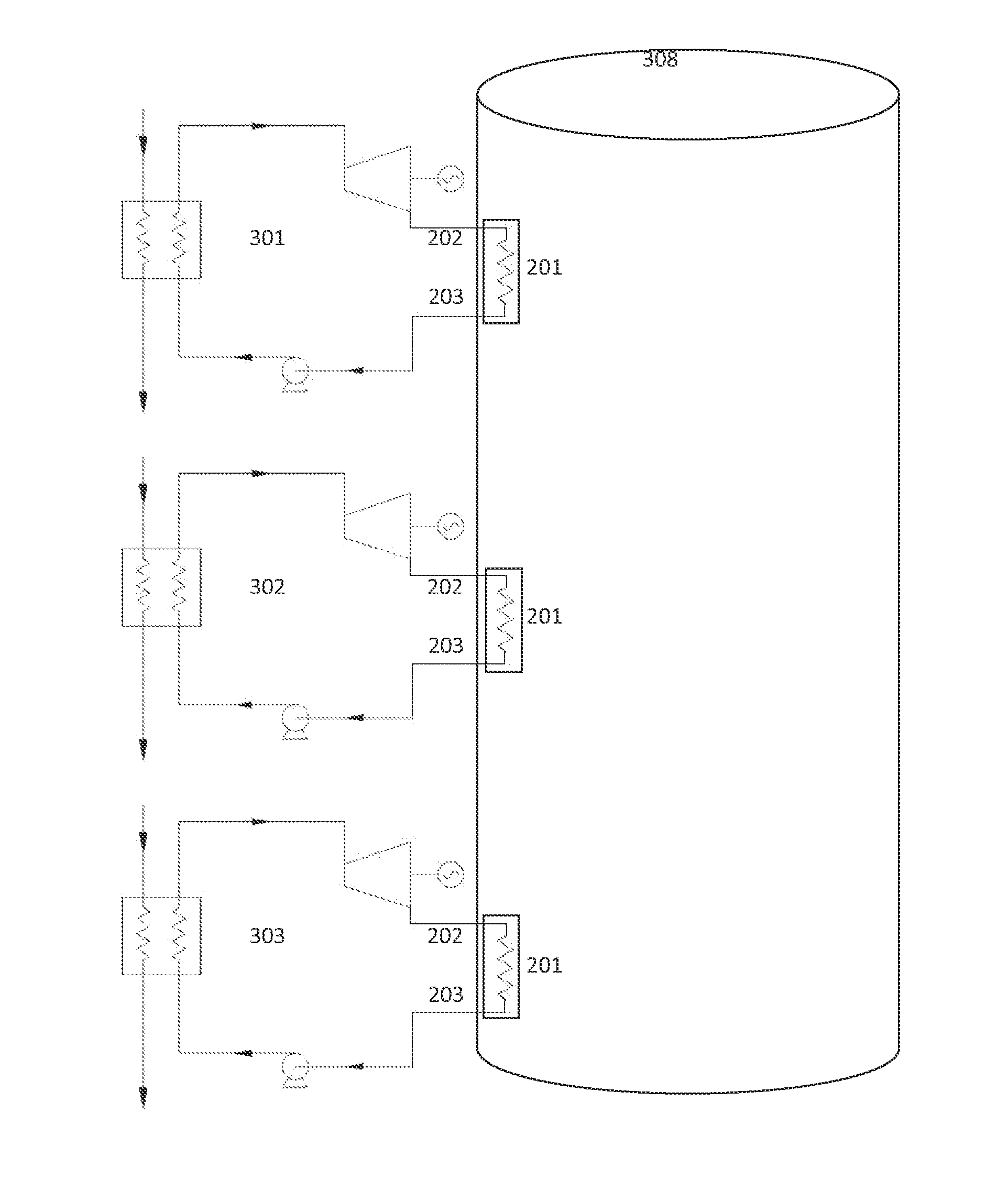
[0049]The process of anaerobic digestion is well known in the art. Certain strains of bacteria, in the absence of oxygen, are employed to break down, or digest, certain biodegradable material including food, yard, or other waste into combustible gasses consisting of methane, hydrogen, and other trace components, as well as a residual solid effluent. This effluent, or sludge, contains ammonia, phosphorous, potassium, and other trace materials and is beneficial to agriculture as a supplemental enrichment fertilizer for soil.

[0050]The anaerobic digestion process involves three basic stages involving different microorganisms, and the temperature of the cultures can play a very significant role in the efficiency of the digestion process. Mesophilic digestion, occurring at medium temperatures, can be applied to discrete batches of biodegradable waste while thermophilic digestion, occurring at higher temperatures, may preferably be utilized on a continuous basis. Although the anaerobic dig...


PUM


Abstract

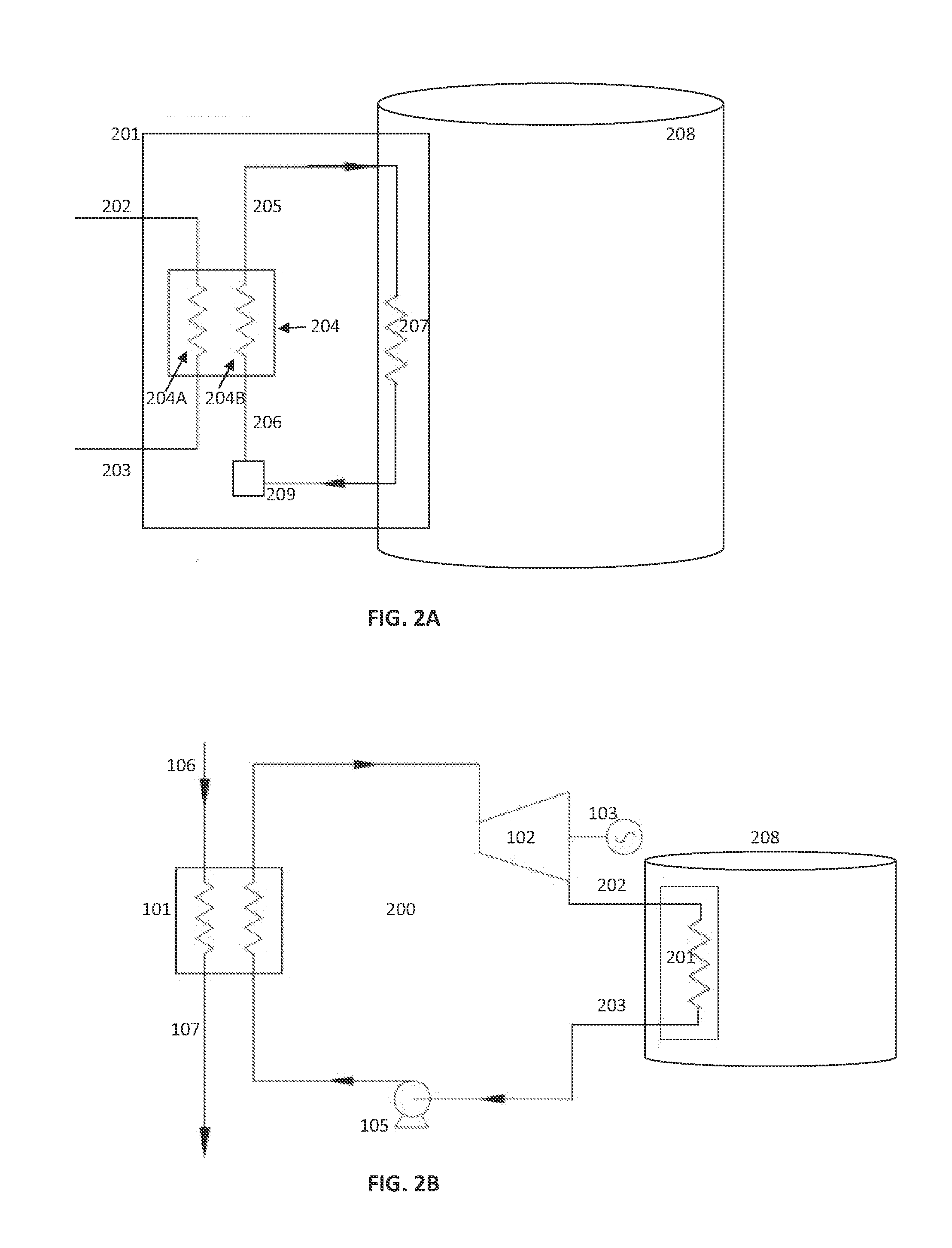
Apparatus, systems and methods are provided for the improved use of waste heat recovery systems which utilize the organic Rankine cycle (ORC) to generate mechanical and / or electric power from waste heat of large industrial machines (prime movers) generating power from biofuel such as biogas produced during the anaerobic digestion process. Waste heat energy obtained from prime mover(s) is provided to one or more ORC system(s) which are operatively coupled to separate electrical generator(s). The ORC system includes a heat coupling subsystem which provides the requisite condensation of ORC working fluid by transferring heat from ORC working fluid to another process or system, such as anaerobic digester tank(s), to provide heat energy that enhances the production of fuel for the prime mover(s) without requiring the consumption of additional energy for that purpose.

Description

RELATED APPLICATIONS [0001]This application claims priority from the applicants' prior U.S. Provisional Patent Application entitled Improved Heat Utilization in ORC Systems, Ser. No. 61 / 594,168, filed Feb. 2, 2012, which Application is hereby incorporated by reference. In this regard, in the event of inconsistency between anything stated in this specification and anything incorporated by reference in this specification, this specification shall govern.FIELD OF INVENTION [0002]The present invention relates to the apparatus, systems, and methods of utilizing organic Rankine cycle systems for the generation of power from waste heat sources.BACKGROUND [0003]Many physical processes are inherently exothermic, meaning that some energy previously present in another form is converted to heat by the process. While the creation of heat energy may be the desired outcome of such a process, as with a boiler installed to provide radiant heat to a building using a network of conduits which circulat...

Claims


Application Information

Patent Timeline
Patent Type & Authority Applications(United States)
IPC IPC(8): F01K25/08
CPCF01K25/08Y02E20/14F01K23/064F01K23/04F01K9/003C05F17/40C05F17/50F01K13/02F01K23/10F01K25/10F03G7/04Y02E50/30Y02W30/40Y02P20/129Y02P20/145C12M21/04C12M29/24C12M43/04C12M43/08F01K7/16F01K13/00F01K13/006F01K23/18F01K25/06Y02E10/46Y02E20/16Y02T10/12
Inventor WAIN, HANSWILLIAMS, DAVID
Owner BITZER US
Why Eureka
Eureka Blog
Learn More