
Integration of a liquefied natural gas liquefier with the production of liquefied natural gas

a technology of liquefied natural gas and liquefier, which is applied in the direction of liquefaction, lighting and heating apparatus, and separation processes, etc., can solve the problems of high energy requirements for purifying renewable methane, high energy consumption of biogas/landfill gas, and difficult production of alternative fuels from low-grade methane opportunity sources, etc., to achieve the effect of reducing the capital cost of plant construction, reducing net power consumption, and reducing the total

Inactive Publication Date: 2013-08-15
LINDE AG
View PDF9 Cites 22 Cited by
  • Summary
  • Abstract
  • Description
  • Claims
  • Application Information

AI Technical Summary

Benefits of technology

The patent text describes the integration of two separation systems, which results in more efficient use of power and lower costs compared to typical nitrogen recovery units. This integration eliminates the need for additional equipment, such as vacuum pumps and recycle compressors, making the construction of the plant less expensive. The invention can also be applied to other sources of methane, such as bio-digesters.

Problems solved by technology

Production of alternative fuels from low-grade methane opportunity sources, such as biogas and landfill gas, is challenging but has great value.
Further, the energy that is required to purify the renewable methane is significant.
The cleanup of biogas / landfill gas is both capital and power intensive because it contains a large number of trace and bulk contaminants in fairly large concentrations.
However, these processes can be expensive in both capital and operating costs and it is important to minimize these costs to achieve an economically viable process.
LNG production is particularly challenging since all condensable contaminants including carbon dioxide must be removed to low ppm levels.
The presence of these compounds makes traditional liquefaction techniques without their removal more difficult and will increase the power costs of the liquefaction process.
Molecular gate and vacuum swing adsorption processes do not remove hydrogen so liquefaction systems that depend on these methods for the removal of inert compounds will have additional concerns over increased power consumption.

Method used


Image

  • Integration of a liquefied natural gas liquefier with the production of liquefied natural gas
  • Integration of a liquefied natural gas liquefier with the production of liquefied natural gas
  • Integration of a liquefied natural gas liquefier with the production of liquefied natural gas

Examples


Embodiment Construction

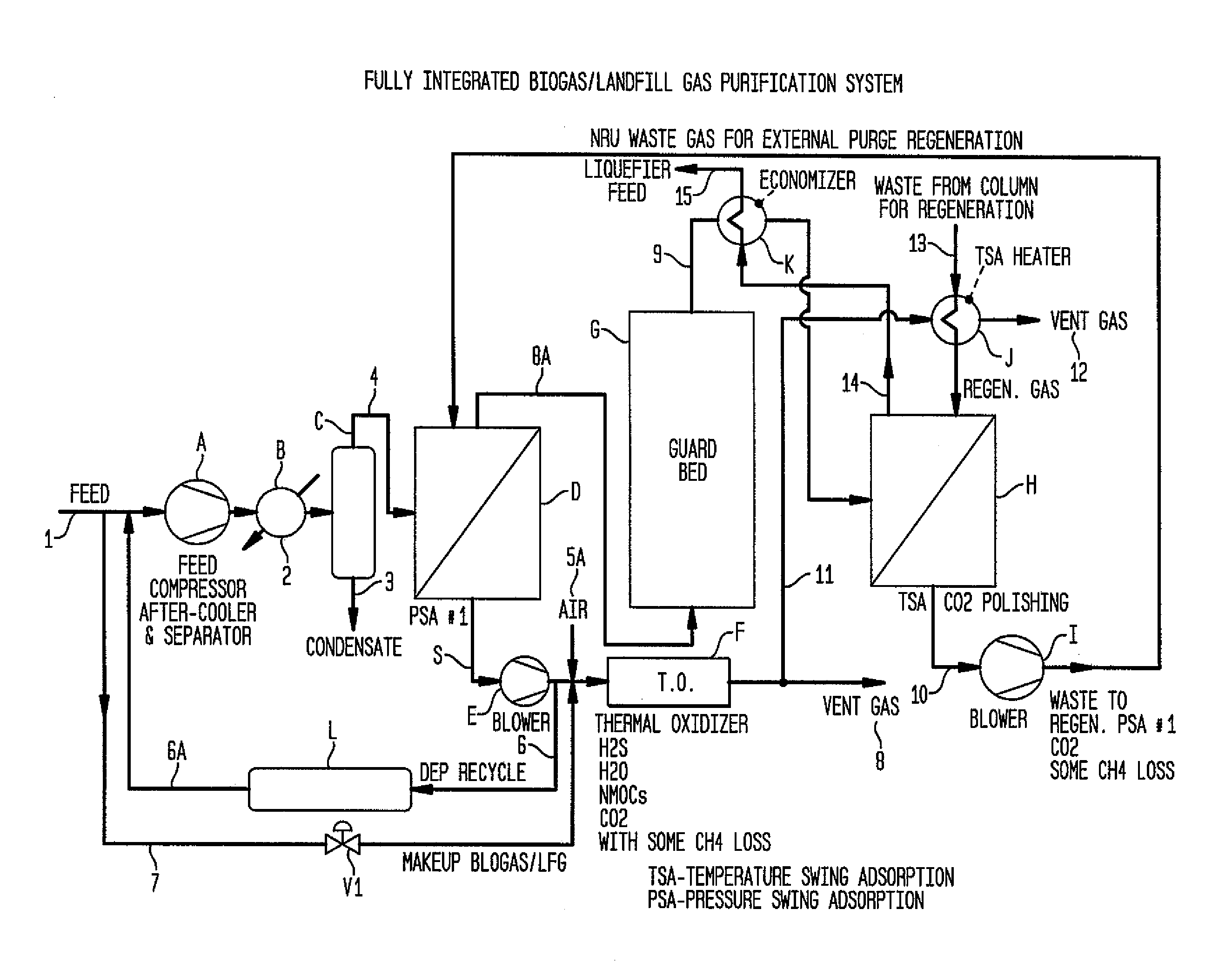
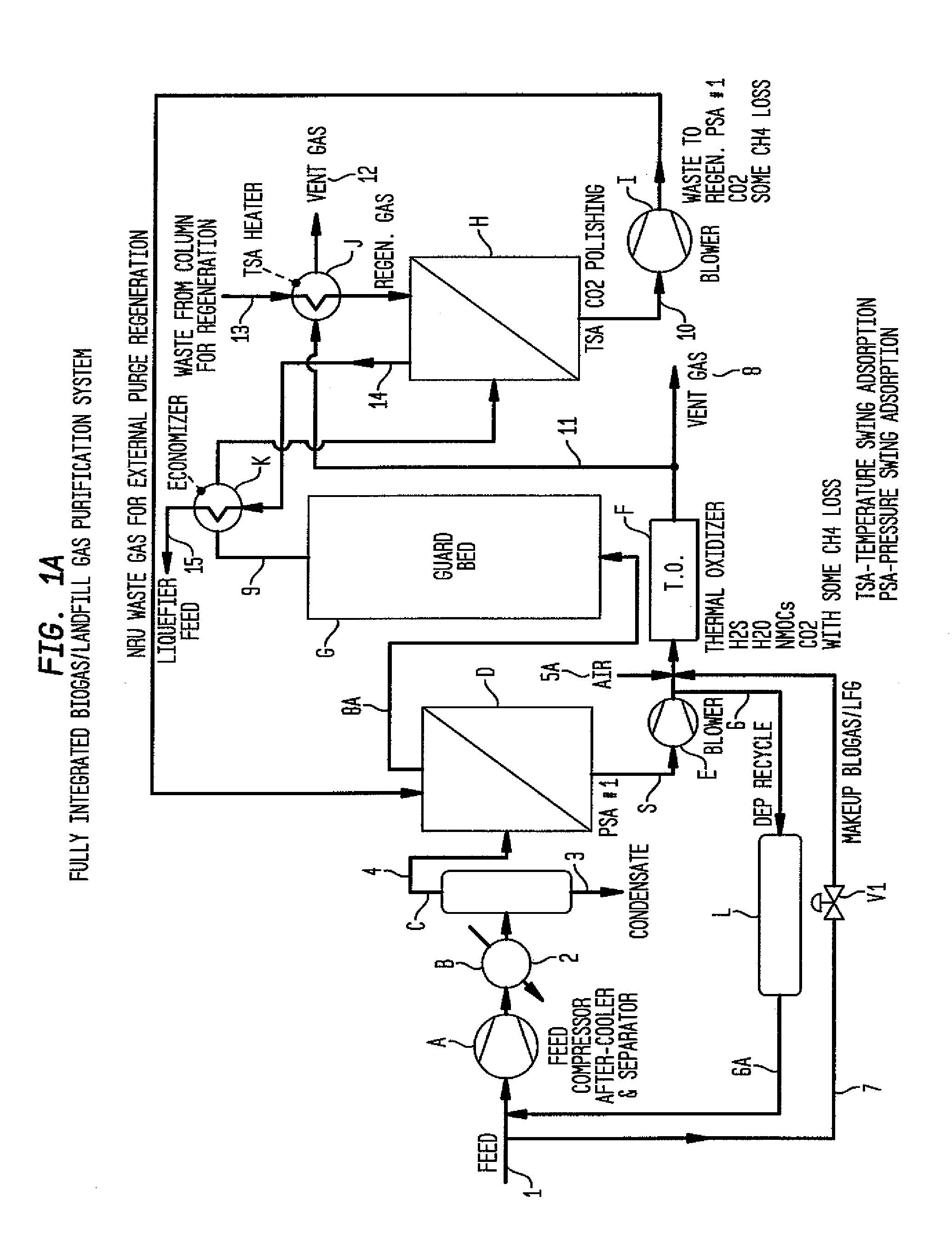
[0025]FIG. 1a is a schematic of a fully integrated biogas / landfill gas purification system according to the invention. Line 1 feeds a biogas or liquefied fuel gas into a feed compressor A which will pressurize the feed gas for entry into the purification system. The compressed feed gas will enter an after-cooler B through line 2 and be fed to a separator C where liquid condensate will be separated from the feed gas stream through line 3 as well as heavier volatile organic compounds (VOCs), dust and other particles. The feed gas stream will leave the separator C through line 4 and be fed to the first pressure swing adsorption unit D.

[0026]The feed gas stream will be separated in the first pressure swing adsorption unit D into a methane gas stream and a stream containing by-products such as hydrogen sulfide, water, carbon dioxide NMOCs and some methane. The pressure swing adsorption unit D contains an adsorbent or adsorbents capable of separating methane from the impurities present in...


PUM


Abstract

A method for integrating a liquefied natural gas liquefier system with production of liquefied natural gas from a methane-containing gas stream. The liquefied natural gas is produced by feeding a methane-containing gas stream through a heat exchanger to a distillation column and liquefying the natural gas while capturing the gaseous nitrogen. The liquefied natural gas is captured and the nitrogen gas is recovered, fed through the heat exchanger to recover cold and purified.

Description

CROSS REFERENCE TO RELATED APPLICATIONS[0001]This application claims priority from U.S. Provisional Patent Application Ser. No. 61 / 543,863 filed Oct. 6, 2011.BACKGROUND OF THE INVENTION[0002]The invention is the integration of a liquefied natural gas (LNG) liquefier system with the production of LNG from biogas or landfill gas.[0003]Production of alternative fuels from low-grade methane opportunity sources, such as biogas and landfill gas, is challenging but has great value. Alternative fuels derived from such sources include liquefied natural gas, liquid to compressed natural gas (LCNG), small-scale hydrogen production form low-grade natural gas and pipeline injection of compressed, purified natural gas. The primary natural gas sources of interest are landfill gas and biogas, particularly digester gas, wastewater treatment off-gas, coal seam methane as well as other opportunistic biogas sources.[0004]Renewable methane can be recovered from a number of sources, such as anaerobic dig...

Claims


Application Information

Patent Timeline
IPC IPC(8): B01D53/047
CPCY02E50/346F25J2290/32F25J1/0022F25J1/004F25J1/0052F25J1/0212F25J1/0291F25J3/0209F25J3/0233F25J3/0257F25J2200/02F25J2200/70F25J2205/60F25J2205/66F25J2210/66F25J2215/04F25J2220/62F25J2245/42F25J2270/12F25J2270/66B01D53/047B01D53/0462B01D2257/504B01D2258/05Y02E50/30Y02C20/40
Inventor SETHNA, RUSTAM H.POTTHOFF, RICHARDPAGES, GUILLAUME
Owner LINDE AG
Learn More