
Solid ammonia storage and delivery material

a technology of ammonia storage and ammonia discharge, applied in the direction of ammonia handling/storage, exhaust treatment, copper ammonia complexes, etc., can solve the problems of ammonia emission, nosub>x /sub>x is noxious, and the use of conventional so-called three-way exhaust catalysts for automobiles is impossibl

Inactive Publication Date: 2013-09-05
AMMINEX EMISSIONS TECH
View PDF3 Cites 7 Cited by
  • Summary
  • Abstract
  • Description
  • Claims
  • Application Information

AI Technical Summary

Problems solved by technology

Particularly, vehicles equipped with diesel engines or other lean burn engines offer the benefit of improved fuel economy, but suffer from the drawback of increased formation of NOx being noxious and which must be eliminated from the exhaust gas.
However, catalytic reduction of NOx using conventional so-called three-way exhaust catalysts for automobiles is impossible because of the high content of oxygen in the exhaust gas.
Injection of a too large amount of reducing agent will cause emission of ammonia with the exhaust gas whereas injection of a too small amount of reducing agent causes a less than optimum conversion of NOx.
However, there are several disadvantages related to the use of aqueous urea as the reducing agent.
Altogether, these difficulties may limit the possibilities of using SCR technology in abatement of pollution from NOx, particularly in connection with mobile units.
Transporting ammonia as a pressurized liquid is hazardous as the container may burst or a valve or tube might break in an accident giving a discharge of poisonous / lethal gaseous ammonia.
However, the use of the ammonia storage media known from WO 99 / 01205 suffers from various draw-backs hampering a wide-spread use in the automotive industry.
The vapour pressure of ammonia above a solid salt phase is e.g. about 1 bar at room temperature and atmospheric pressure for calcium octa ammine chloride and strontium octa ammine cchloride complexes rendering the use somewhat complicated due to the high pressures that must be taken into account in view of the toxicity of ammonia.
Having such a high partial pressure of ammonia, the handling and trans-portation of the saturated storage material is still difficult and also dangerous.

Method used


Image

  • Solid ammonia storage and delivery material
  • Solid ammonia storage and delivery material
  • Solid ammonia storage and delivery material

Examples


example 1

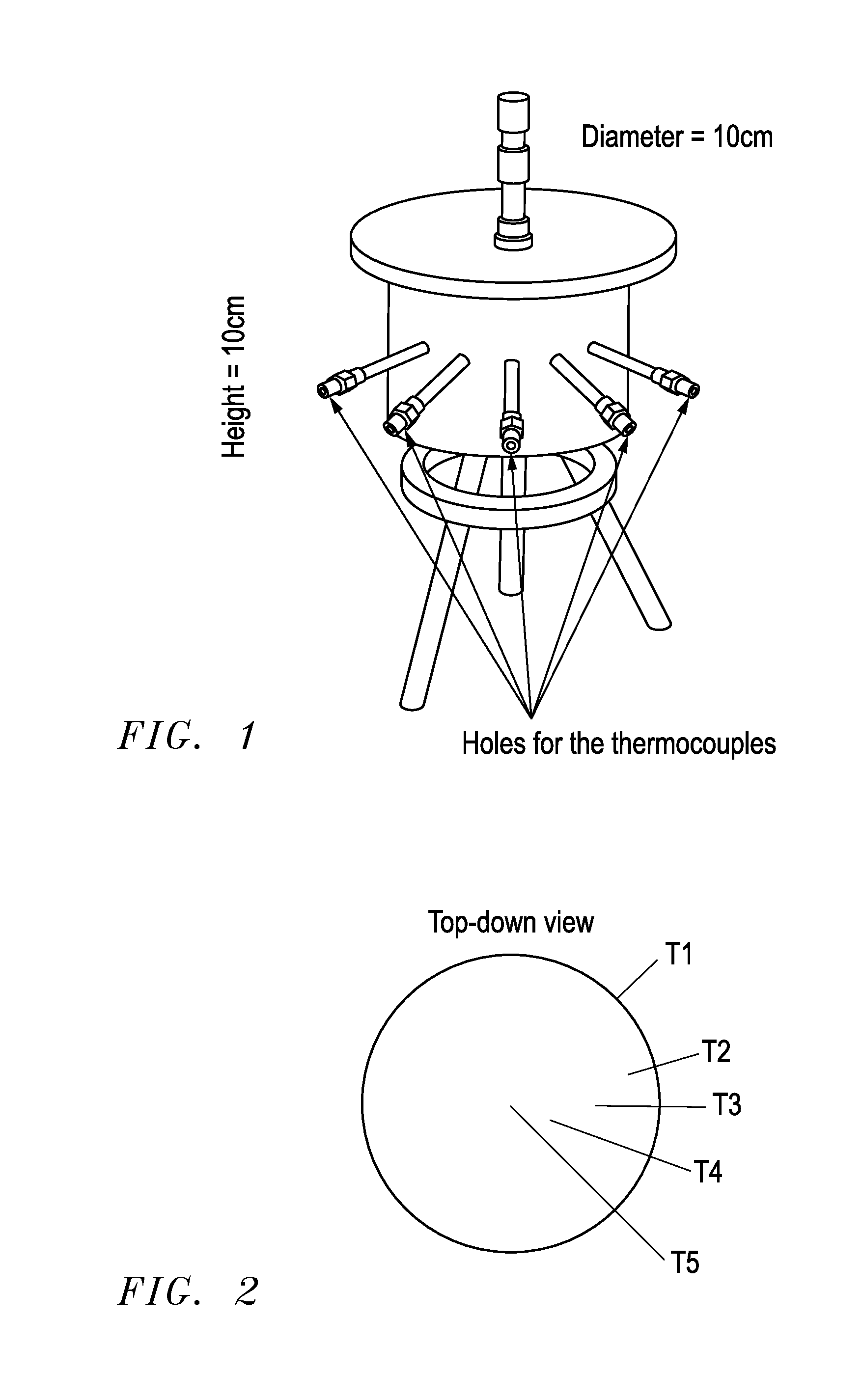
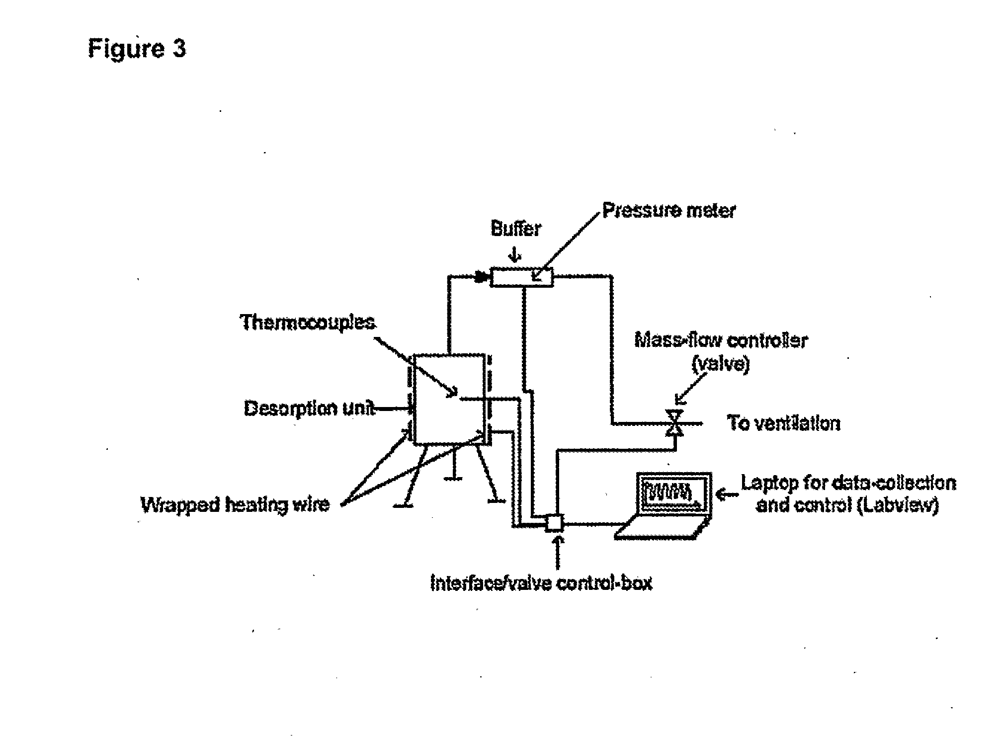
[0078]An ammonia delivery device was made from stainless steel in the form of a cylindrical container, having the dimensions 2R0=H=10 cm, where R0 is the inner radius and H is the height of the reactor. A photograph of the device is shown in FIG. 1. The device was provided with five wells for insertion of thermocouples placed perpendicular to the tangent of the reactor circumference for determining the radial temperature distribution. Furthermore, a thermocouple was placed on the outer wall to measure the actual temperature of the heated steel wall. Ammonia-saturated MgCl2 powder (258.8 grams) was then placed and compacted slightly by manual pressure to a bed density of approximately 331 kg / m3. A thin sheet of quartz cotton was placed on top of the salt to prevent any grains from being carried out of the reactor. As desorption of ammonia from the complex requires elevated temperature, a heating wire was wrapped around the reactor and thermal insulation (Rockwool) was placed on top o...

example 2

Compression of Solid Ammonia Storage Medium

[0089]FIG. 7 schematically shows a device compression of the solid ammonia delivery material for the preparation of cylindrical tablets (dimensions: 13 mm in diameter; 10 mm high). In this embodiment, the solid ammonia delivery material was compressed in a chamber by applying a pressure of 2-4 tons / cm2 using a piston compressing the powdered saturated storage material. When the piston was removed, the delivery material was in the desired shape of e.g. a tablet, a cylinder or a rod, and had a density above 80% of the theoretical crystal density.

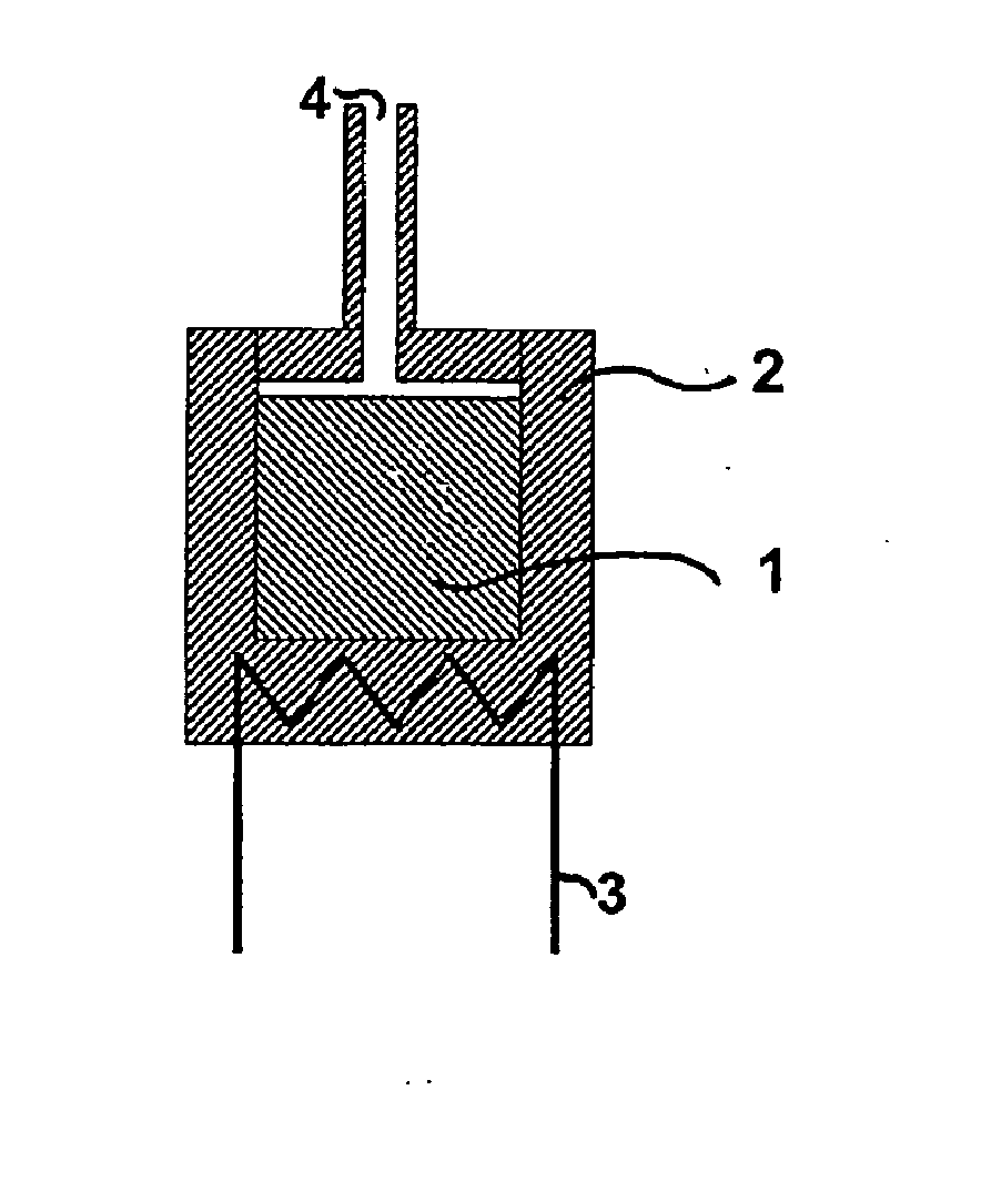
[0090]FIG. 8 schematically shows an embodiment of an ammonia delivery device of the invention for desorption of the compressed delivery material. In this embodiment, one or more tablets of solid ammonia delivery material 1 are placed in a container 2, which can be heated by a heating device 3. Desorbed ammonia leaves the container through a nozzle 4. Heat for the heating device 3 may be provided by e....

example 3

Comparison of the Use of Ammonia Delivery Devices of the Invention and Urea-Technology

[0095]By calculating the amount of NOx (assumed to be pure NO) generated per kilometre in a model fuel (taken as pure n-octane, ρ=696.8 kg / m3), the corresponding driving distance for a given amount of ammonia or urea can be found.

[0096]Based on the EURO 3 standards (The European Parliament, 1998) as well as by the values used by some researchers (Hyundai Motor Co.: Choi et al., 2001), the assumed NOx concentrations and the fuel economies are: 150 ppm and 10 km / litre for stoichiometric combustion (typically gasoline) and 300 ppm and 15 km / litre for lean burn combustion (λ=1.5, typically diesel).

[0097]Taking 1 litre (or 696.8 g) of fuel as a basis of calculations the generated NOx per. kilometre would be 5.87-10−2 mole / km or 0.18 g / km for stoichiometric combustion, while for lean burn combustion (λ=1.5), the NOx emission is 1.15-10−2 mole / km or 0.34 g / km.

[0098]In the below table 3 is shown the requir...


PUM

PropertyMeasurementUnit
vapour pressureaaaaaaaaaa
densityaaaaaaaaaa

Abstract

Disclosed is a method for the selective catalytic reduction of NOx in waste / exhaust gas by using ammonia provides by heating one or more salts of formula Ma(NH3)nXz, wherein M represents one or more cations selected from alkaline earth metals and transition metals, X represents one or more anions, a represents the number of cations per salt molecule, z represents the number of anions per salt molecule, and n is a number of from 2 to 12, the one or more salts having been compressed to a bulk density above 70% of the skeleton density before use thereof.

Description

CROSS-REFERENCE TO RELATED APPLICATIONS[0001]The present application is a divisional of U.S. application Ser. No. 11 / 658,986, which is a National Stage of PCT / DK2005 / 000516, filed Aug. 3, 2005, which claims priority of Danish patent applications PA 2004 01179, filed Aug. 3, 2004, PA 2005 00166, filed Feb. 3, 2005, and PA 2005 00926, filed Jun. 25, 2005. The entire disclosures of the aforementioned patent applications are expressly incorporated by reference herein.BACKGROUND OF THE INVENTION[0002]1. Field of the Invention[0003]The present invention relates to the storage of ammonia in a solid form using metal ammine complexes and delivery there from. The invention also relates to the use of ammonia stored in a solid form as the reducing agent in selective catalytic reduction (SCR) of NOx in exhaust gases from combustion processes, to methods for producing such complexes and to an ammonia delivery device comprising such complexes.[0004]2. Description of the Related Art[0005]Current en...

Claims


Application Information

Patent Timeline
Patent Type & Authority Applications(United States)
IPC IPC(8): B01D53/56
CPCB01D53/90B01J20/28011B01J20/046B01J20/3035C01C1/006C01F5/00C01G3/14C01G9/00C01G45/00C01G49/00C01G51/12C01G53/12C01P2006/10F01N3/2066F01N2610/02F01N2610/06F01N2610/10Y02T10/24B01D53/565B01D53/9431F17C11/00Y02T10/12B01D53/86B01J20/04B01J20/28
Inventor CHRISTENSEN, CLAUS HVIIDJOHANNESSEN, TUEQUAADE, ULRICHNORSKOV, JENS KEHLETSORENSEN, RASMUS ZINK
Owner AMMINEX EMISSIONS TECH
Learn More