High brightness illumination system and wavelength conversion module for microscopy and other applications

a technology of illumination system and wavelength conversion module, which is applied in the direction of optics, lighting and heating equipment, instruments, etc., can solve the problems of short life, environmental hazards, and temporal variation of output power

Inactive Publication Date: 2013-11-28
EXCELITAS CANADA
View PDF15 Cites 50 Cited by
  • Summary
  • Abstract
  • Description
  • Claims
  • Application Information

AI Technical Summary

Benefits of technology

[0018]Advantageously, in a preferred embodiment, the optical element is shaped as a cone, which may be a simple cone, a truncated cone or other conical shape. The reflector means comprises a conical surface thereof, which is coated with an optical coating having a high reflectance, preferably >94%, at the converted wavelength. The surface also preferably has a high reflectance at the laser wavelength. A conical shape is simple to manufacture and provides effective extraction of the converted wavelength.
[0020]In other embodiments, the optical element comprises a body comprising said wavelength conversion medium having a shape, such as a simple geometric shape, comprising one of a cylinder, a cube, a rectangle, a cone, and a pyramid, or combinations thereof, and the reflector means comprises a reflective facet or facets of the shape, that are highly reflective, i.e. coated with a reflective coating, which may be a broadband coating or a dichroic coating, to direct photoluminescence emission generated within the wavelength conversion medium towards the output aperture of the optical element. For example, the wavelength conversion medium may comprise a cylindrical portion of the body coupled to a reflector portion of the body of an optical medium having a conical shape, and wherein at least facets of the reflector portion and walls of the cylindrical portion comprises a coating having a high reflectivity at the converted wavelength and at the laser wavelength. For wavelength conversion elements with tapered reflective surfaces such as provided by a conical or pyramidal reflector geometry for example, which may be a truncated cone, it is advantageous for the reflective facets to be polished and comprise a reflective coating with >94% reflectance at the converted wavelength and at the laser wavelength. Thus, the reflective surfaces of the optical element effectively direct the converted wavelength towards the output aperture. When the wavelength conversion element has high reflectivity at the laser wavelength, it increases the path length of the laser beam within the conversion medium and permits a more complete absorption of the laser energy by the conversion medium.
[0022]For wavelength conversion elements of a cubic or cylindrical shape, i.e. with parallel opposing facets, it is advantageous that reflective surfaces have a surface structure or texture to produce diffuse reflectance and reduce specular reflection, thereby reducing probability of cavity modes. Beneficially, the reflectance of these surfaces is preferably >94% reflectance, at both the laser wavelength and at the converted wavelength.
[0023]More complex shapes may be used but these tend to add to design complexity and manufacturing costs. A conical or pyramidal wavelength conversion element is relatively simple to manufacture and provides good performance.
[0031]Alternatively, the optical concentrator comprises a compound parabolic concentrator, or other complex profile concentrator. The optical concentrator may be an air concentrator. Alternatively, it may be a dielectric concentrator that preferably comprises an optical medium that is index matched to that of the optical element. The latter helps to improve extraction of light and also assists with thermal dissipation.

Problems solved by technology

Problems associated with these conventional lamp technologies, however, include short lifetime, temporal variation of the output power, high voltage operation (typically kilovolts required to strike the lamp), and use of mercury, which is now seen as an environmental hazard and is in the process of undergoing regulations to limit use in numerous countries throughout the world.
Nevertheless, despite technological advances in LED technology, high brightness LED light sources are not available to cover all wavelengths required for illumination systems for microscopy or fluorescence microscopy, for example.
In particular, LED devices still do not match the radiance of traditional arc-lamps in some regions of the visible spectrum, especially in the 540 to 630 nm spectral band.
While laser diodes are a special class of LEDs that can produce high intensity, narrow bandwidth, coherent illumination for some wavelengths, these are also not available for all required wavelengths.
Also, speckle or optical artifacts produced by coherent illumination may be undesirable for some applications.
The performance of these systems may be limited by quantum yield of the wavelength conversion process, and by the need for thermal management to dissipate heat from the LEDs and from the fluorescent material.
Systems that require combining output of multiple LEDs to obtain sufficient brightness over a particular spectral range may be quite large and require significant cooling.
However, these arrangements do not effectively address requirements for microscope illumination systems.
Moreover, because of the different form factor and light distribution pattern of the radiation output of LED light sources and arc lamps, the requirements for optical systems for effectively coupling of illumination systems using LED light sources are different from those using conventional arc lamps.

Method used


Image

  • High brightness illumination system and wavelength conversion module for microscopy and other applications
  • High brightness illumination system and wavelength conversion module for microscopy and other applications
  • High brightness illumination system and wavelength conversion module for microscopy and other applications

Examples


first embodiment

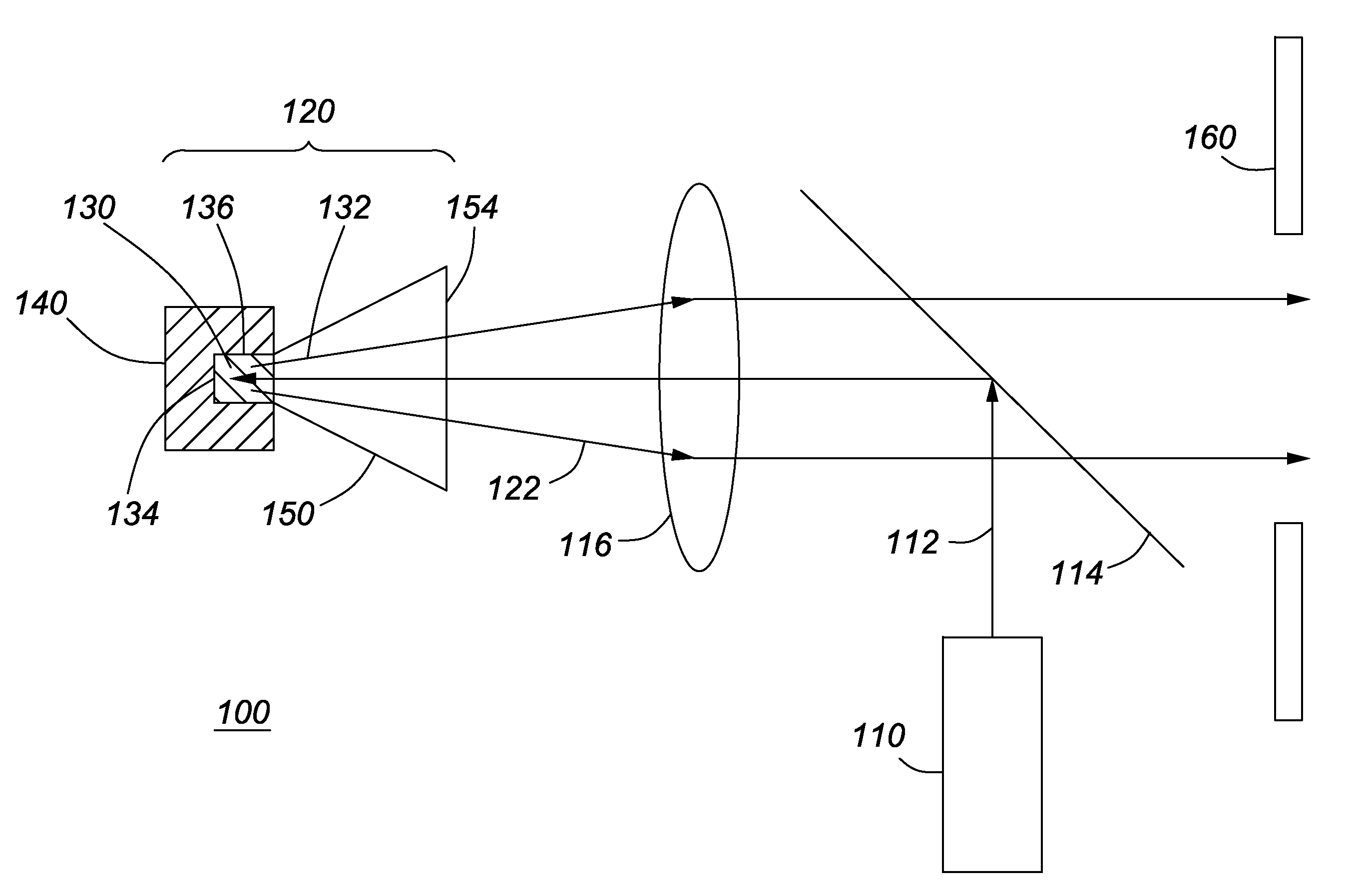
[0046]A schematic diagram of an illumination system 100 according to the invention is shown in FIG. 1. It comprises a laser light source 110 and an optical wavelength conversion module 120, which comprises an optical element 130 mounted within a support or holder 140 of thermally conductive material, and an optical concentrator 150. The laser source 110 generates optical radiation 112 that is collimated or focused and directed towards to the optical element 120 via optical components comprising a dichroic minor 114, lens 116 and the optical concentrator 150. The laser radiation 112 enters the optical element 130 of the wavelength conversion module 120, via a surface 132 of optical element 130 that mates with the aperture 152 of optical concentrator 150. The optical element 130 comprises a wavelength conversion medium 131, i.e. a fluorescent material that absorbs optical radiation 112 from the laser source 110 and emits photoluminescence or fluorescence 122 at a different wavelength,...

second embodiment

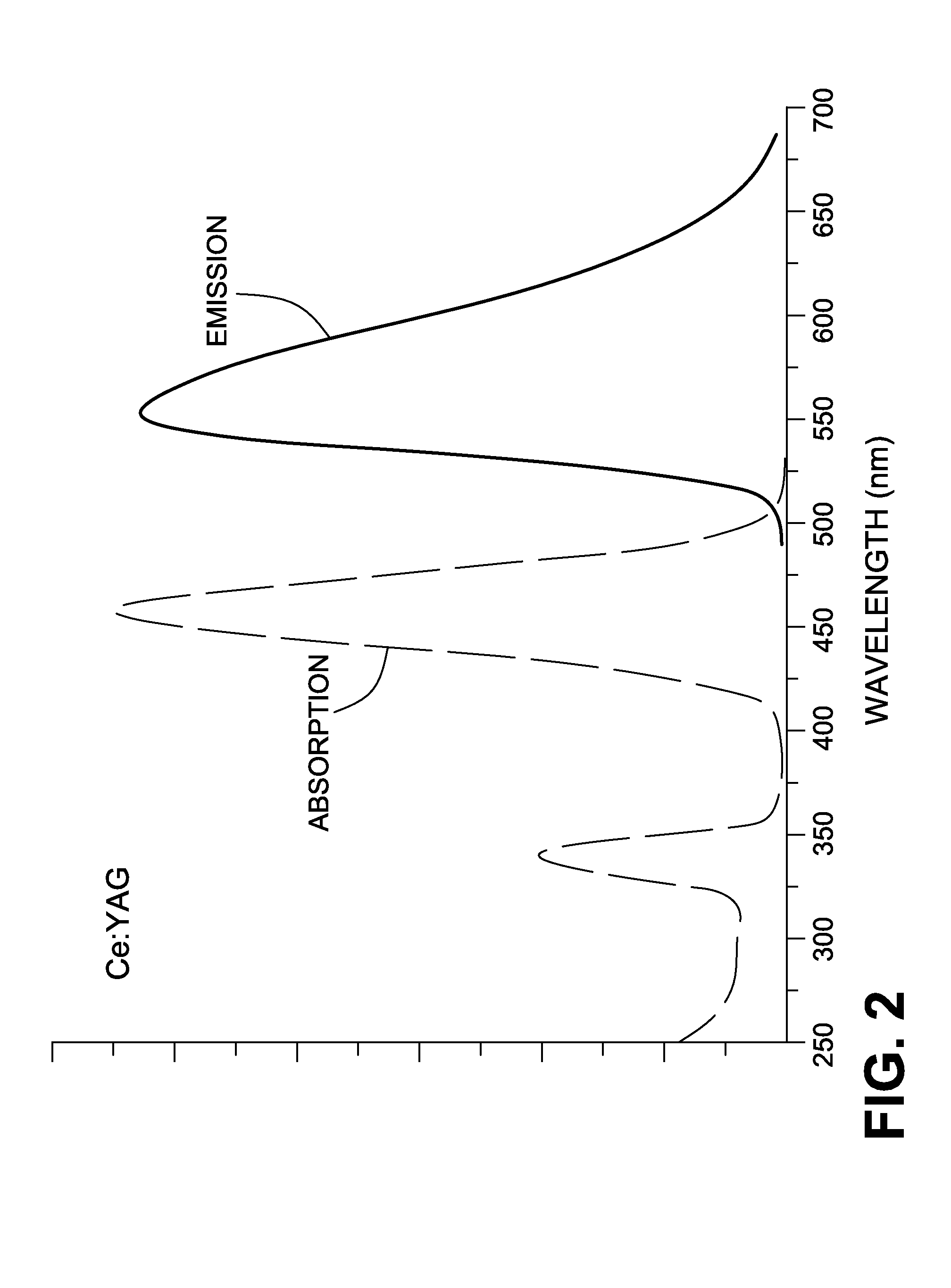
[0071]Alternatively, a combination of shapes and materials could be used to improve optical performance over the simple cube or cylindrical rod. This could be designed so one could benefit both from cost and ease of manufacturability and acceptable optical performance. For example, in a wavelength conversion module 220 a preferred design for the shape of the body of the optical element 230 of the fluorescent material comprises a short cylindrical portion 231 that is bonded with or contiguous with a conical reflector portion 233, as shown in FIG. 9 and FIG. 10. The cylindrical portion 231 would be a selected fluorescent material e.g. Ce:YAG to provide fluorescence at the desired wavelength. The conical portion 233 could also be the same material, or would preferably be a glass material, or another material, such as sapphire or undoped YAG, that has a similar index of refraction as the fluorescent material 231 and is transparent at the wavelength of the photoluminescence. These varia...


PUM

PropertyMeasurementUnit
reflectanceaaaaaaaaaa
diameteraaaaaaaaaa
diameteraaaaaaaaaa

Abstract

An illumination system comprising a laser light source and a wavelength conversion module for generating high brightness illumination by photoluminescence. The wavelength conversion module comprises an optical element comprising a wavelength conversion medium, set in a mounting for thermal dissipation, and an optical concentrator. The shape of the optical element and its reflective surfaces provides improved light extraction at the converted wavelength, and allows for more effective cooling. It provides a compact light source with a configuration suitable for applications that require high brightness and narrow bandwidth illumination at a selected wavelength, e.g. for fluorescence microscopy, or other applications requiring étendue-limited optical fiber coupling. The system, which preferably uses a solid state laser diode, provides an alternative to conventional arc lamps, and addresses limitations of other available solid state LED light sources to provide high brightness at some wavelengths, particularly in the 580nm to 630nm range.

Description

CROSS-REFERENCE TO RELATED APPLICATIONS[0001]This application claims priority from U.S. Provisional patent application No. 61 / 651,130, filed May 24, 2012, which is incorporated herein by reference in its entirety.FIELD OF THE INVENTION[0002]This invention relates to high brightness light sources for illumination systems for applications such as microscopy and fluorescence microscopy, and particularly for fiber coupled illumination systems.BACKGROUND[0003]There is a need for high optical radiance illumination sources to provide optical fiber coupled illumination for microscopy and other applications. Conventional illumination systems typically utilize short arc lamps such as high pressure mercury, metal halide, and xenon. These lamps are capable of very high radiance and are therefore suitable sources for étendue limited fiber optic coupled illumination systems.[0004]Problems associated with these conventional lamp technologies, however, include short lifetime, temporal variation of ...

Claims


Application Information

Patent Timeline
Patent Type & Authority Applications(United States)
IPC IPC(8): G02F1/35F21V9/16
CPCG02F1/353F21V9/16G02B21/06F21K9/68
Inventor PAQUETTE, MICHEL
Owner EXCELITAS CANADA
Why Eureka
Try Eureka