Surfactant effects on efficiency enhancement of luminescent particles

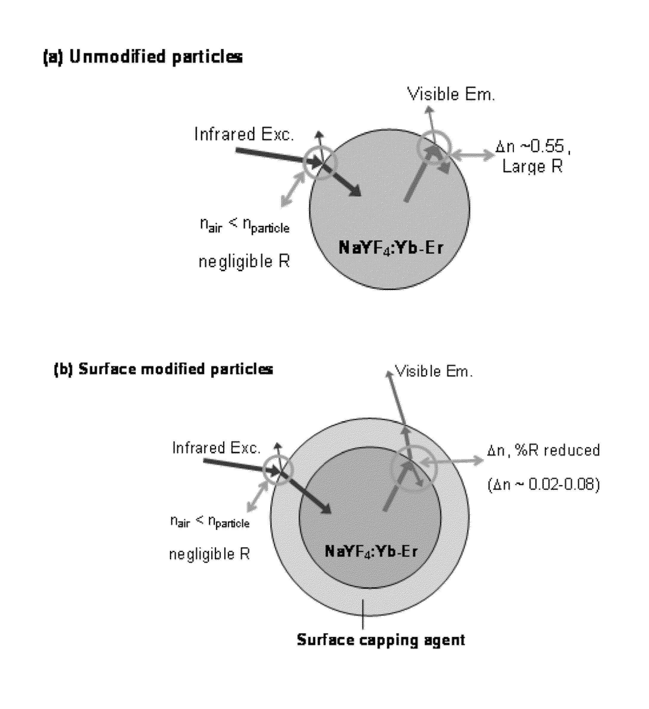
a technology of surfactant and luminescent particles, which is applied in the direction of luminescent compositions, chemistry apparatuses and processes, etc., can solve the problems of significant reduction of emitted light from the light-emitting phosphor core, high reflectance loss of emitted light, etc., and achieve the effect of reducing the refractive index mismatch

Inactive Publication Date: 2013-12-05
RUTGERS THE STATE UNIV
View PDF2 Cites 20 Cited by
  • Summary
  • Abstract
  • Description
  • Claims
  • Application Information

AI Technical Summary

Benefits of technology

[0009]This invention is based, at least in part, on the utilization of surface capping agents that reduce t...

Problems solved by technology

The large refractive index mismatch between the core light-emitting phosphor particle and surrounding medium leads to high reflectance losses...

Method used


Image

  • Surfactant effects on efficiency enhancement of luminescent particles
  • Surfactant effects on efficiency enhancement of luminescent particles
  • Surfactant effects on efficiency enhancement of luminescent particles

Examples


example 1

Hydrothermal Synthesis of NaYF4:Yb—Er Upconversion Phosphors

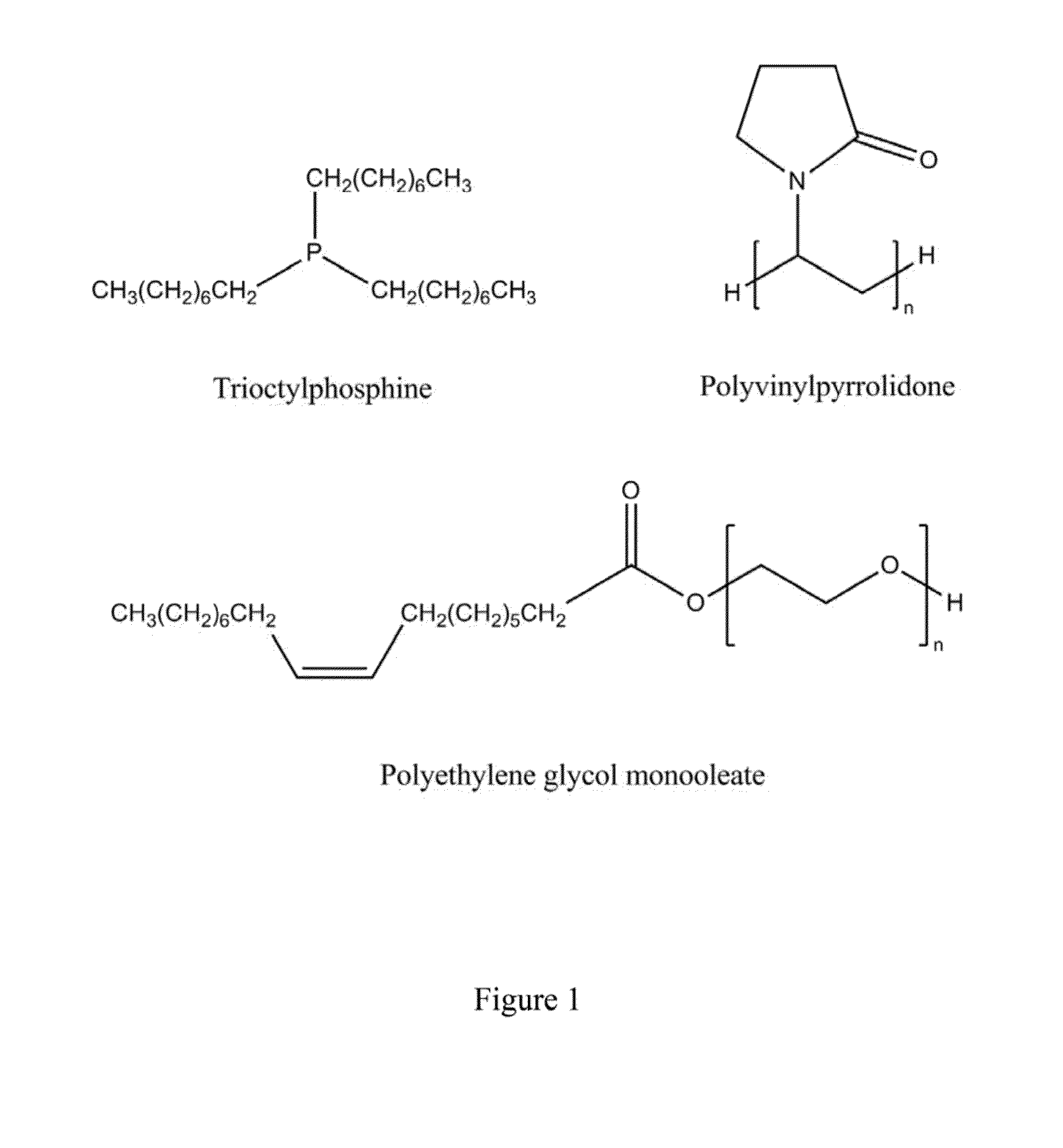
[0036]Stoichiometric amounts of rare earth nitrates (Sigma Aldrich, St. Louis, Mo.) were mixed with 1.5 times excess sodium fluoride in about 70 mL of water:ethanol mixture (80:20 v / v) and various additives for 30 min to synthesize NaY0.78Yb0.20Er0.02F4 particles. 2×10⁻⁴; moles which corresponds to 0.1 mL, 0.1 mL and 8 g of trioctylphosphine, polyethylene glycol monooleate (PEG monooleate, average Mn of about 460 g / mol) and polyvinylpyrrolidone (average Mn of about 40,000 g / mol), respectively from Sigma Aldrich was added to the reaction mix. This mixture was next transferred to a 125 mL. Teflon liner and heated to about 240° C. for 4 h in a Parr pressure vessel (Parr Instrument Company, Moline, Ill.). The as-synthesized particles were washed three times in deionized water by centrifuging (Beckman-Coulter Avanti J-26 XP, Fullerton, Calif.) and dried at 70° C. in air in a mechanical convection oven (Thermo Scientific Thermoly...

example 2

Powder Characterization by X-ray Diffraction

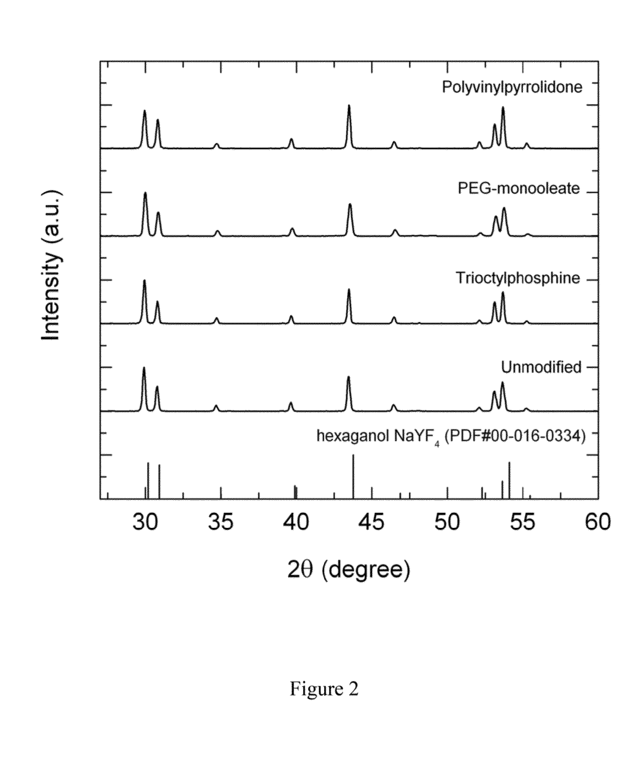
[0037]Powder x-ray diffraction (XRD) patterns were obtained with a resolution of 0.04° / step and 2 sec / step with the Siemens D500 (Bruker AXS Inc., Madison, Wis.) powder diffractometer (40 kV, 30 mA), using Cu Kα radiation (μ=1.54 Å). Powder diffraction files (PDF) from International Centre for Diffraction. Data (ICDD, Newtown Square, Pa.) PDF#97-005-1917 for hexagonal NaYF4 was used as reference.

[0038]From the XRD profiles as shown in FIG. 2, pure hexagonal-phase NaYF4:Yb—Er powders were synthesized using the hydrothermal method and different surfactants. No statistically significant difference in grain sizes were observed based on the full width at half maximum of the various diffraction peaks for the different powders. Using the Scherrer equation, the average grain size estimated for each of the different powders shown in FIG. 2 was about 41±5 nm. Since the concentration of rare earths in the host lattice has a significant effect on the ...

example 3

Powder Characterization by X-ray Photoelectron Spectroscopy

[0039]X-ray photoelectron spectroscopy (XPS) measurements were performed using XSAM 800 KRATOS apparatus with a 127 mm radius concentric hemispherical analyzer (CHA). An Al Kα radiation with a photon energy of 1486.6 eV was used as x-ray source; and photoelectrons were detected by the CHA operated in the fixed retarding ratio mode FRR5 (survey scans), and in the fixed analyzer transmission modes FAT20 or FAT40 (detail scans) with the pass energies of 20 and 40 eV, respectively, XPS quantification of the atomic fraction for each component was determined by comparing relative intensities of photoelectron peaks together with the corresponding sensitivity factors, and assuming their total intensities to be 100%. The atomic fraction was subsequently normalized to the integrated intensity of Na (2s) peaks to allow for comparisons between samples. The measurements were performed under UHV conditions with a residual pressure of abou...


PUM


Abstract

Disclosed are luminescent compositions having luminescent particles coated by a surface capping agent. Luminescent particles include rare earth doped phosphors, semiconductor quantum dots, and organic phosphors. Surfactants include macromolecules, polypeptides, polysaccharides, and polymers. Rare earth doped phosphors have host compositions and rare earth dopants, wherein the host compositions include NaYF4, LaF3, YF3, CeF3, CaF2, CsCdBr3, and Y2O3, and wherein the rare earth dopants include Cs, Pr, Nd, Sm, Er, Gs, Tb, Dy, Ho, Er, Tim, Yb, and combinations of two or more of these. The refractive index mismatch of the luminescent compositions and surrounding medium is less than about 0.1. Also disclosed are methods of making the luminescent compositions, luminescent devices and displays containing the luminescent compositions, uses of the luminescent compositions in particle imaging velocimetry, and uses of the luminescent compositions as contrast agents for disease monitoring.

Description

CROSS-REFERENCE TO RELATED APPLICATIONS[0001]This application claims the benefit of U.S. Provisional Application Ser. No. 61 / 652,374, filed May 29, 2012, which is hereby incorporated by reference.STATEMENT REGARDING FEDERAL FUNDED RESEARCH[0002]This invention was made with government support under grant number ONR-N00014-08-1-0131 awarded by the Defense Advanced Research Projects Agency. The government has certain rights in the invention.FIELD OF THE INVENTION[0003]The present invention relates to the field of surface-capped (i.e., surfactant coated) luminescent particles.BACKGROUND OF THE INVENTION[0004]Luminescent materials emit over a wide range of electromagnetic radiation such as the x-ray, ultraviolet, visible, infrared regions upon suitable excitation or supply of energy. The type of luminescence can be distinguished based on the type of excitation energy, for example, cathodoluminescence, photoluminescence, x-ray luminescence, electroluminescence, sonoluminescence, chemolumi...

Claims


Application Information

Patent Timeline
IPC IPC(8): C09K11/77
CPCC09K11/7773
Inventor RIMAN, RICHARD E.TAN, MEI-CHEE
Owner RUTGERS THE STATE UNIV
Why Eureka
Try Eureka