

Heat dissipating substrate, and element equipped with same
a technology of heat dissipation substrate and heat dissipation layer, which is applied in the direction of printed circuit stress/warp reduction, electrical apparatus construction details, and semiconductor/solid-state device details. it can solve the problems of resin having insufficient heat dissipation performance, deteriorating the element itself, and affecting the heat dissipation performance of the resin. excellent
- Summary
- Abstract
- Description
- Claims
- Application Information
AI Technical Summary
Benefits of technology
Problems solved by technology
Method used
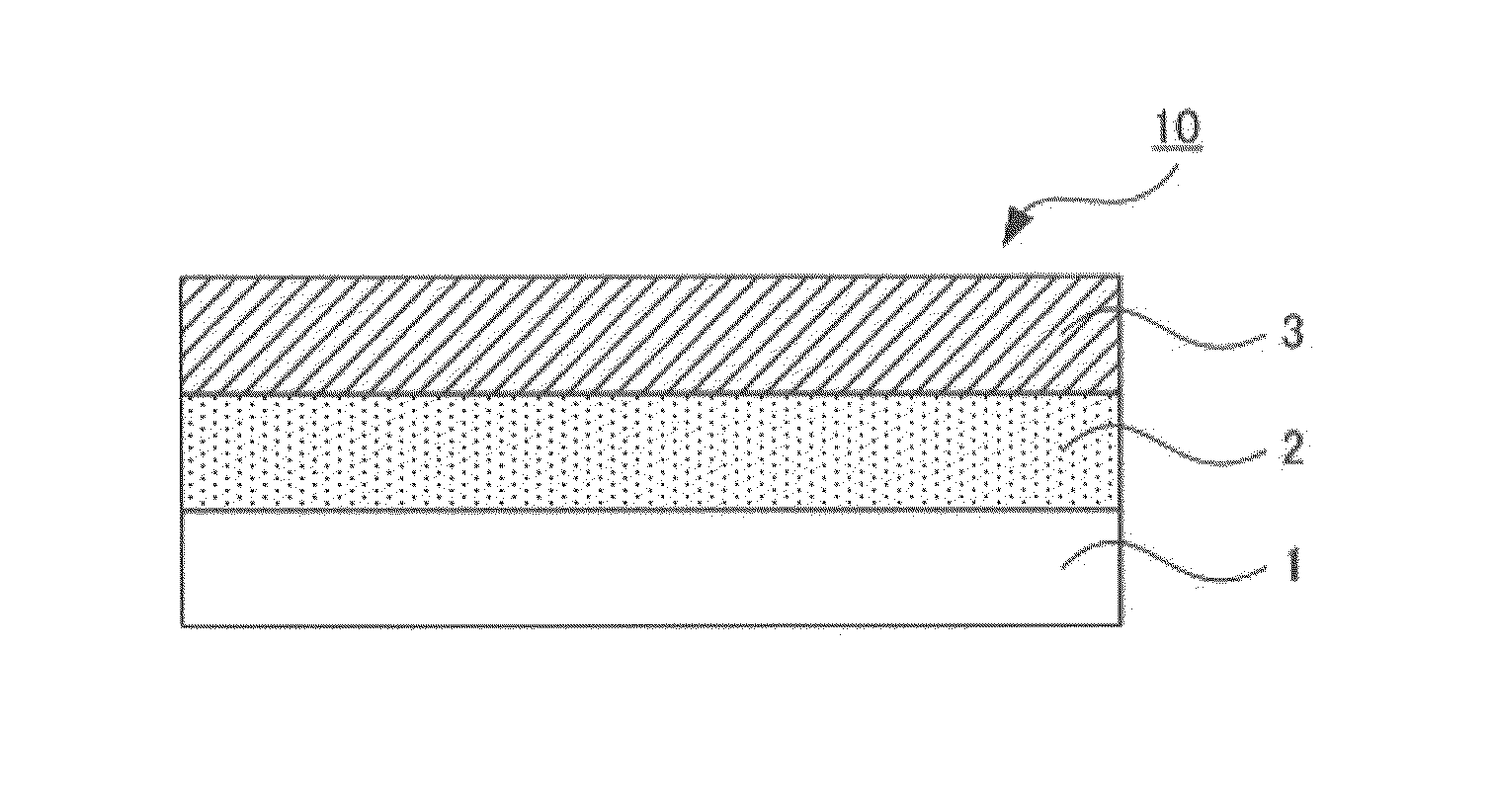
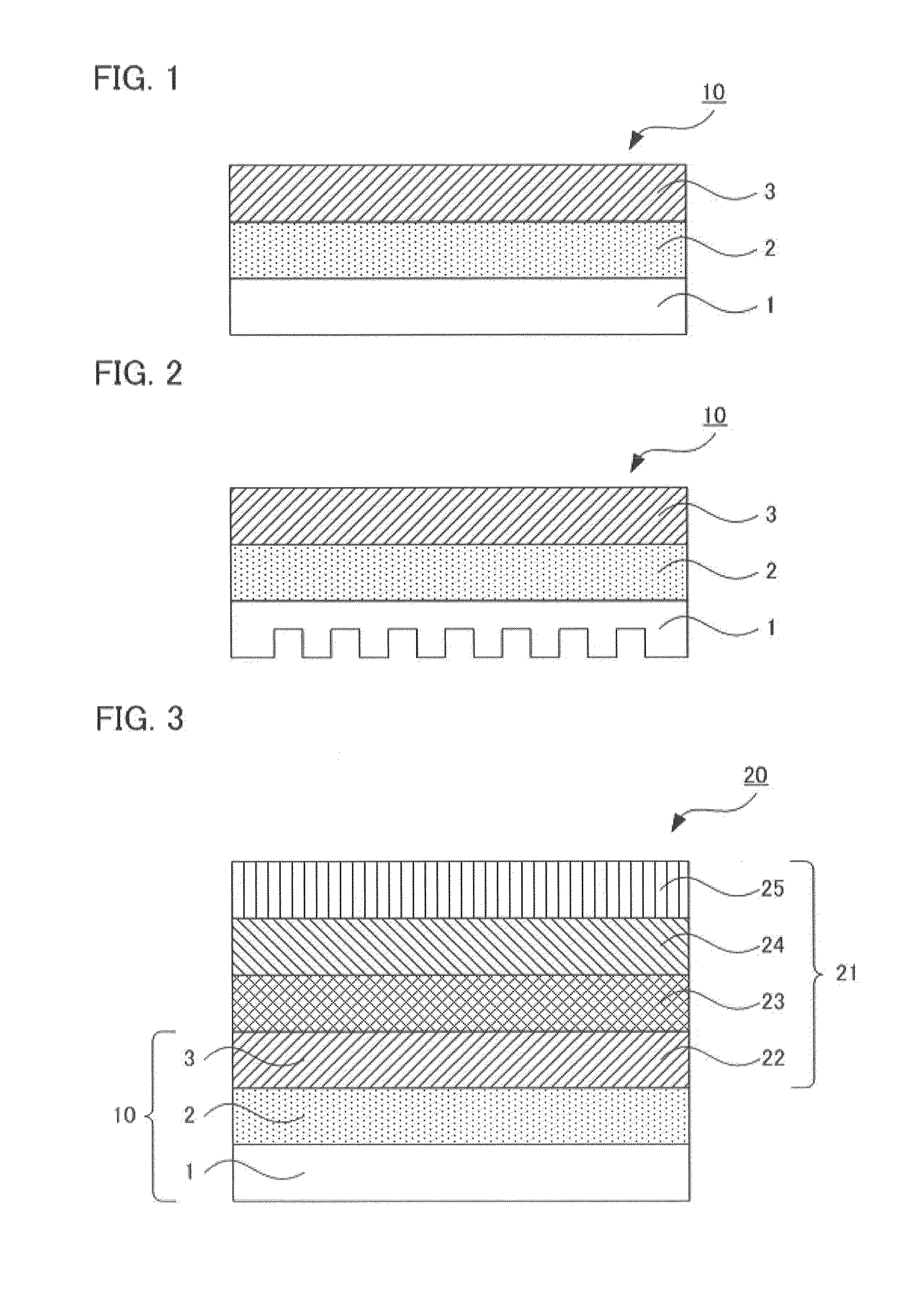
Image

Examples
examples
[0216]Hereinafter, the invention will be specifically described by using Examples thereof, and Comparative Examples.
1. Preparation of Insulating-Layer-Forming Resin Solution
(1) Production Example 1
[0217]4.0 g (20 mmol) of 4,4′-diaminodiphenyl ether (ODA), and 8.65 (80 mmol) g of p-phenylenediamine (PPD) were charged into a 500-mL separable flask, and these components were dissolved in 200 g of dehydrated N-methyl-2-pyrrolidone (NMP). Under nitrogen gas flow, this reaction system was stirred while heated in an oil bath in the state that the liquid temperature was monitored with a thermocouple so as to be 50° C. It was verified that these components were completely dissolved, and subsequently thereto was bit by bit added 29.1 g (99 mmol) of 3,3′,4,4′-biphenyltetracarboxylic dianhydrate (BPDA) over 30 minutes. After the end of the addition, the system was stirred at 50° C. for 5 hours. Thereafter, the system was cooled to room temperature to yield a polyimide precursor solution 1.
(2) P...
example 1
[0259]A die coater having a coating width of 150 mm was used to coat the polyimide precursor solution 1 onto an area of 150 mm square of a copper base (manufactured by Furukawa Electric Co., Ltd.) having a thickness of 150 μm and cut into a size of 16 cm square in such a manner that after cured, the coated solution 1 would have a thickness of 10 μm. The workpiece was dried in the atmosphere in an oven of 80° C. for 60 minutes. Thereafter, the workpiece was subjected to heat treatment at 350° C. (temperature-raising rate: 10° C. / minute) in nitrogen atmosphere for 1 hour (followed by natural cooling). In this way, a laminated body 1 was produced in which an insulating layer was formed.
[0260]Next, a wiring layer was formed onto the insulating layer of the laminated body 1 as follows.
[0261]First, the whole of the insulating-layer-formed side of the laminated body was subjected to surface-roughening treatment under conditions described below, and washed with water. Furthermore, a catalys...
example 2
[0300]A die coater having a coating width of 150 mm was used to coat the polyimide precursor solution 1 onto an area of 150 mm square of a copper base (manufactured by Furukawa Electric Co., Ltd.) having a thickness of 150 μm and cut into a size of 16 cm square in such a manner that after cured, the coated solution 1 would have a thickness of 20 μm. The workpiece was dried in the atmosphere in an oven of 80° C. for 60 minutes. Thereafter, the workpiece was subjected to heat treatment at 350° C. (temperature-raising rate: 10° C. / minute) in nitrogen atmosphere for 1 hour (followed by natural cooling). In this way, a laminated body 2 was produced in which an insulating layer was formed.
[0301]Next, a wiring layer was formed in the same way as in Example 1 except that the laminated body 2 was used. In this way, a heat dissipating substrate was produced.
PUM
| Property | Measurement | Unit |
|---|---|---|
| thickness | aaaaa | aaaaa |
| thickness | aaaaa | aaaaa |
| volume resistivity | aaaaa | aaaaa |
Abstract
Description
Claims
Application Information