
Split Cycle Phase Variable Reciprocating Piston Spark Ignition Engine

a reciprocating piston, phase variable technology, applied in the direction of engine components, machines/engines, engine controllers, etc., can solve the problems of poor overall thermodynamic efficiency, slow flame propagation, increase in induction fluid temperature, etc., to achieve higher chamber pressure, high thermodynamic efficiency, and high charge density

Inactive Publication Date: 2014-04-03
SETH CHANDAN KUMAR +1
View PDF4 Cites 13 Cited by
  • Summary
  • Abstract
  • Description
  • Claims
  • Application Information

AI Technical Summary

Benefits of technology

This patent describes a new type of engine that improves upon existing designs. It uses a four-stroke internal combustion engine with two pistons, cylinders, and crankshafts. The compressor unit only does the intake and compression strokes, while the power unit does the expansion and exhaust strokes. The compressor unit uses air with a higher specific heat ratio, resulting in higher chamber pressure at the end of compression. The fuel is injected into the air through a crossover gas passage and combustion is initiated by a sparkplug. Unlike conventional engines, the working chambers retain no residual burnt gas, leading to higher charge density and better combustion. The engine also has a phase altering mechanism that can change the phase relation between the crankshafts and between the compressor and power units for better expansion chamber environment. Additionally, the engine has an un-throttled intake system for avoiding pumping loss and allows for a high over-expansion cycle at part load engine operating mode. The engine is simple in design and controllable with existing methods.

Problems solved by technology

In spark ignition (SI) engine, there are various practical constraints in the traditional engine design that produces poor overall thermodynamic efficiency, especially at regular drive conditions of a vehicle.
Because the SI engine load control is essentially done by quantitative control in induction of combustible mixture, the regular drive condition or low engine load condition in a SI engine suffers from various problems like: 1) considerable charge dilution and increase in induction fluid temperature by residual burnt gas wherein, higher induction temperature limits compression ability of the working fluid, 2) low initial and peak combustion chamber pressure, 3) slow flame propagation in combustion chamber, 4) incomplete combustion and 5) pumping loss.
All the remaining strokes are power consuming strokes.
Though, beyond certain restriction point the compression ratio induces knocking which is detrimental to the engine.
As a result, the initial and final combustion chamber pressure drops drastically and this phenomenon affects the cycle thermodynamic efficiency.
At ordinary drive condition this residual gas proportion is substantially higher than it is at heavy load drive condition; hence the charge become considerably diluted and this reduces the flame speed in working fluid and results in poor combustion quality.
Dilution also increases the chances to misfire and so fuel enrichment is needed.
But, fuel lean combustion deteriorates the performance of Three-way Catalytic Converter (TWC).
GDI also needs costly fuel injectors and precise control system.
During the typical driving conditions which generally cover above 90% of the entire drive cycle, the intake manifold pressure remains about 0.5 bar or less, causing considerable drag on the driveshaft and this phenomenon is commonly known as ‘pumping loss’, that adversely affects the engine efficiency.
Hence reduces the combustion flame speed and the engine suffers from unstable combustion which leads to reduction in efficiency and increase in hazardous tailpipe emissions.
As the engine operating condition goes below cruising mode such as the city driving conditions, the efficiency further reduces drastically.
Considering this, if an engine is so downsized to operate with higher specific load during cruising or city driving condition, it could not accelerate or climb steep road well.
As pistons of both of the active and deactivated cylinders are generally connected to a common crankshaft, the deactivated pistons continue to reciprocate within the respective cylinders resulting in undesired friction.
The valves of the deactivated cylinders need specialized controls, which produce further complications.
Managing unbalanced cooling and vibration of variable-displacement engines are other designing challenges for this method.
In most instances, cylinder deactivation is applied to relatively large displacement engines that are particularly inefficient at light load.
As VCR technology alone cannot avoid part load pumping losses, it requires assistance of Variable Valve Technology (VVT).
The VCR technology itself, however, is quite complex to design and manufacture.
But the introduction difficulties remain too high to introduce in a practicable engine.
Therefore, at part load mode when only a fraction of compressed gas is used for combustion, the combustion chamber shape at the time of ignition would be very thin if a favorable chamber pressure and temperature is maintained and this kind of chamber shape is highly unfavorable to carryout a desirable combustion.
Moreover, it is very difficult to retain the temperature and pressure of compressed air stored in the storage tank and so using of the stored compressed air would be very difficult due to its continuously variable pressure-temperature parameters.

Method used


Image

  • Split Cycle Phase Variable Reciprocating Piston Spark Ignition Engine
  • Split Cycle Phase Variable Reciprocating Piston Spark Ignition Engine
  • Split Cycle Phase Variable Reciprocating Piston Spark Ignition Engine

Examples


Embodiment Construction

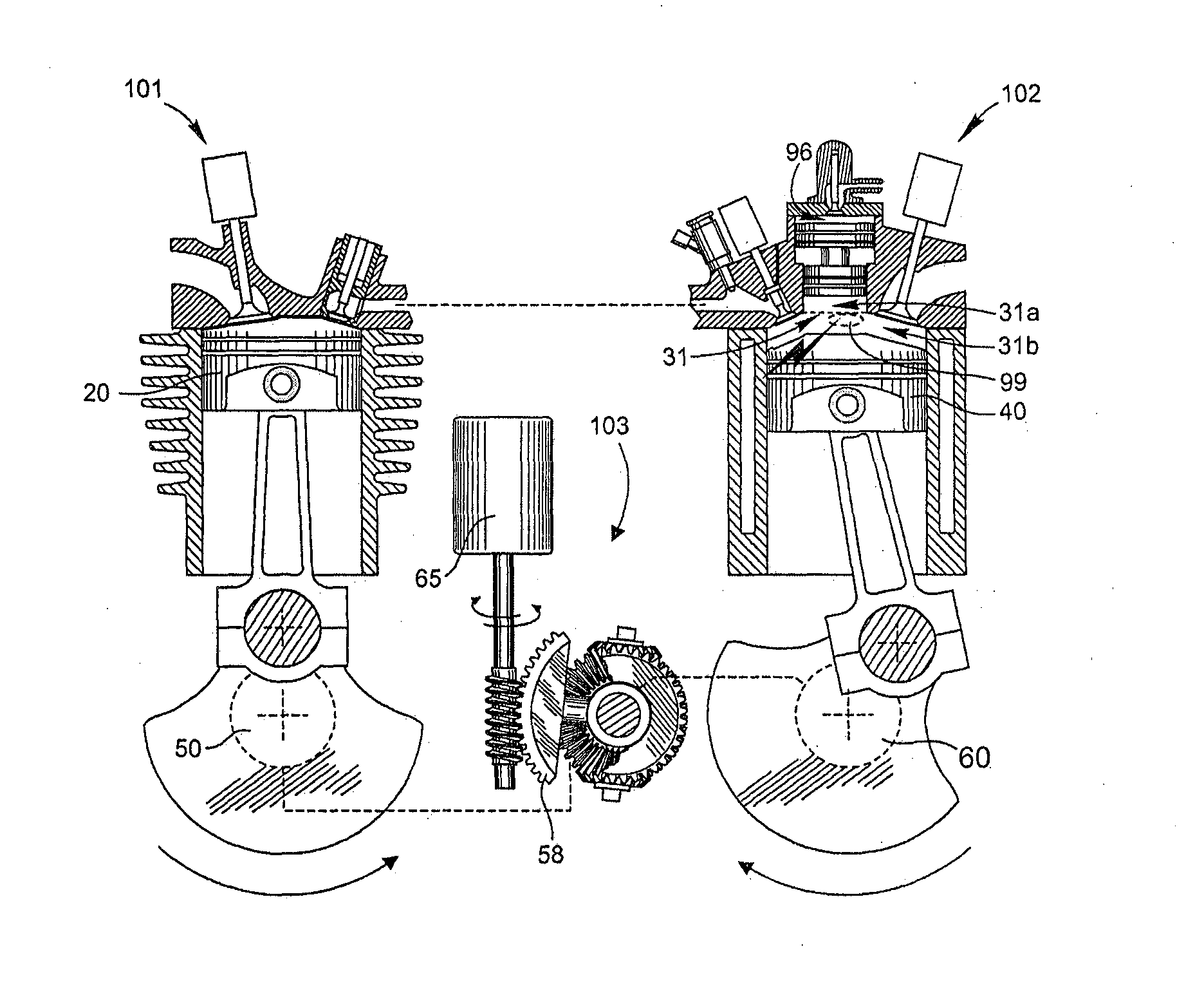
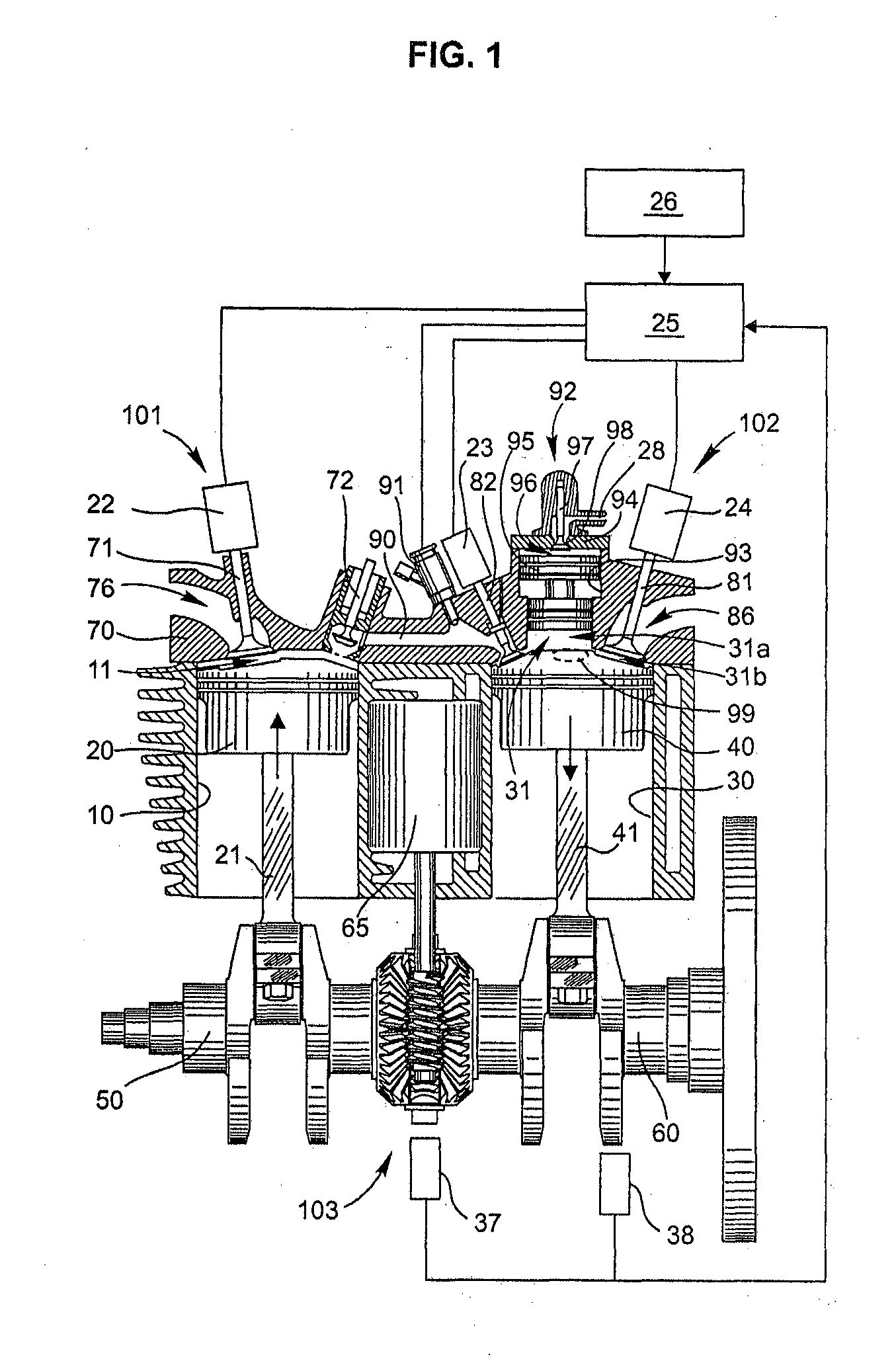
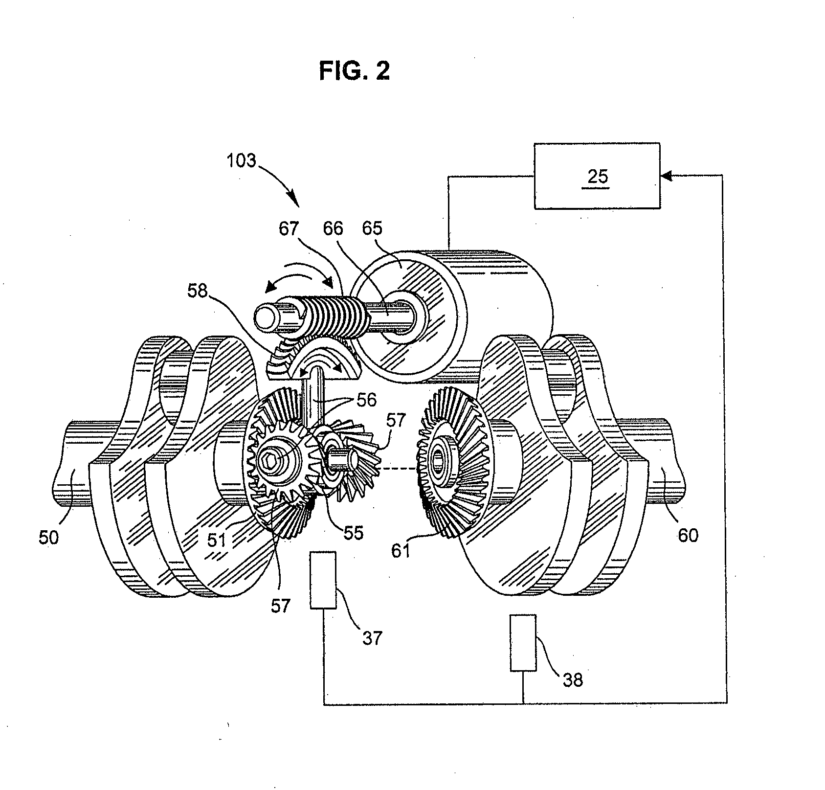
[0027]With reference first to FIG. 1, a split cycle phase variable reciprocating piston spark ignition engine including a first piston cylinder configuration 101 for carrying out the intake and compression strokes of a four stroke engine cycle and a second piston cylinder configuration 102 for carrying out the expansion and exhaust strokes of a four stroke engine cycle. The first piston cylinder configuration 101 may hereinafter be referred to as the Compressor Unit 101 and the second piston cylinder configuration 102 may hereinafter be referred to as the Power Unit 102. The Compressor Unit 101 comprises a cylinder 10 into which a piston 20 reciprocates within a distance determined by a first crankshaft 50 and the Power Unit 102 comprises a cylinder 30 into which a piston 40 reciprocates within a distance determined by a second crankshaft 60. A connecting rod 21 connects the piston 20 to the first crankshaft 50 and a connecting rod 41 connects the piston 40 to the second crankshaft ...


PUM


Abstract

A split cycle phase variable reciprocating piston spark ignition engine comprising a compressor unit having a compression chamber adapted to carry out the intake and compression strokes of a four stroke engine cycle, a power unit having an expansion chamber adapted to carry out the expansion and exhaust strokes of a four stroke engine cycle, a crossover gas passage for transferring compressed gas from the compression chamber to the expansion chamber, an expansion chamber volume modifier to provide nearly full load like combustion chamber condition at all the engine load conditions by means of modifying volume and shape of the expansion chamber, a phase altering mechanism for altering phase relation between the compressor unit and the power unit as a function of engine load variation, an electronic control unit for providing control commands for various electrically operated actuators and motors.

Description

TECHNICAL FIELD OF THE INVENTION[0001]The present invention relates to four stroke cycle internal combustion spark ignition engine and more specifically to a split four stroke cycle spark ignition reciprocating piston engine having at least a pair of piston-crankshaft assembly in which one piston-crankshaft assembly is used for the intake and compression strokes and another piston-crankshaft assembly is used for the power and exhaust strokes, wherein the crankshafts of both the piston-crankshaft assemblies are operatively interconnected by a phase altering mechanism that provide variability in the phase relation between the above mentioned piston-crankshaft assemblies.BACKGROUND OF THE INVENTION[0002]Traditional four-stroke cycle engines are configured with one or more cylinders wherein each one of the cylinders goes through all the four strokes (intake, compression, combustion and exhaust) of a thermodynamic cycle. This basic century old arrangement is still used in a modern vehicl...

Claims


Application Information

Patent Timeline
IPC IPC(8): F01L1/344
CPCF01L1/344F01L1/022F01L1/34F01L1/3442F01L2001/34426F02B33/22F02B39/04F02B75/042F02D15/04F02B75/04
Inventor MISTRY, JIBAN JYOTI
Owner SETH CHANDAN KUMAR
Learn More