
Self-charging electronic devices

a technology of electronic devices and self-charging, which is applied in the field of self-charging electronic devices, can solve the problems of inconvenient or impossible user charging of batteries, limited methods and devices, and limited effective surface area, so as to improve the heat tolerance of electronic devices, improve component performance and battery life, and reduce costs

Active Publication Date: 2014-04-10
PLAIN SIGHT INNOVATIONS LLC
View PDF12 Cites 26 Cited by
  • Summary
  • Abstract
  • Description
  • Claims
  • Application Information

AI Technical Summary

Benefits of technology

The present invention is about a new type of thermophotovoltaic system that can convert thermal energy into electrical energy, which can then be used to power electronic devices. This system is different from existing systems because it uses a microprocessor and a thermophotovoltaic cell that is in communication with the processor. The thermophotovoltaic cell is designed to absorb and separate the incoming radiation, which reduces recombination and photon corrosion. The system can also use multiple sources of thermal energy, such as the processor and other components of the device, to improve performance and battery life. Overall, this invention allows for better utilization of thermal energy and improved performance of self-charging electronic devices.

Problems solved by technology

However, it can be inconvenient or impossible for the user to charge the batteries when, for example, the user is traveling.
In addition, a typical recharge will power the battery for only a limited amount of run time.
However, such methods and devices are limited by small size of many electronic devices, which constrains the effective surface area for absorbing sunlight, as well as the inherent characteristics of solar cells, which require the device to track the sun to maintain consistent exposure to sunlight for stable power output.
Consequently, while the voltage generated by the solar cells can be enough to power less energy demanding devices, the voltage can be insufficient for electronic devices that demand more power.
Thus, there are competing interests between the portability of these devices and the amount of available power.
The effectiveness of using known photovoltaic cells to charge electronic devices is additionally limited by composition and other properties of the cells which frustrate charge separation and transport and permit significant electron-hole pair recombination to occur.
Increasing the thermal energy of such cells further reduces overall photoconversion efficiency (PCE) by lowering charge mobility and promoting additional recombination.
Thermalization inevitably occurs in such applications notwithstanding the relative speed and degree of separation and transport.
Further, almost all of the photons in the flux absorbed by the cell have energies greater than the bandgap energy of silicon, and produce both an electron-hole pair and thermalization losses upon absorption.
Problematically, the performance of electronic devices also degrades in response to elevated temperature.
The integration of conventional solar cells into electronic devices is thus further complicated by the implicit expectation that such devices be exposed to solar radiation.
However, electronic devices generate heat since such devices are comprised in part of components which only use a portion of the charge they receive.
Thus, device manufacturers go to significant lengths to manage heat, in many cases by designing their devices to dissipate heat as a form of waste since it is generally present at low grade temperatures insufficient for known heat recovery technologies to operate cost-effectively, particularly at the scale of a electronic device.
The thermal energy produced by or imparted to known electronic devices, be it from the absorption and inefficient conversion of sunlight or the inefficient use of electrical energy, will eventually dissipate as the system and its surroundings achieve thermal equilibrium.
Historical attempts to access and convert such low grade sources of thermal energy into electricity have been limited and unsuccessful.
The increased use of electronic devices in recent years corresponds to increased fossil fuel consumption.

Method used


Image

  • Self-charging electronic devices
  • Self-charging electronic devices
  • Self-charging electronic devices

Examples


Embodiment Construction

[0034]Reference will now be made in greater detail to a preferred embodiment of the invention, an example of which is illustrated in the accompanying drawings. Wherever possible, the same reference numerals will be used throughout the drawings and the description to refer to the same or like parts.

[0035]In the following description, numerous details are set forth to provide a more thorough explanation of embodiments of the present invention. It will be apparent, however, to one skilled in the art, that embodiments of the present invention can be practiced without these specific details. In other instances, well-known structures and devices are shown in block diagram form, rather than in detail, in order to avoid obscuring embodiments of the present invention. Reference in the specification to “one embodiment” or “an embodiment” means that a particular feature, structure, or characteristic described in connection with the embodiment is included in at least one embodiment of the inven...


PUM


Abstract

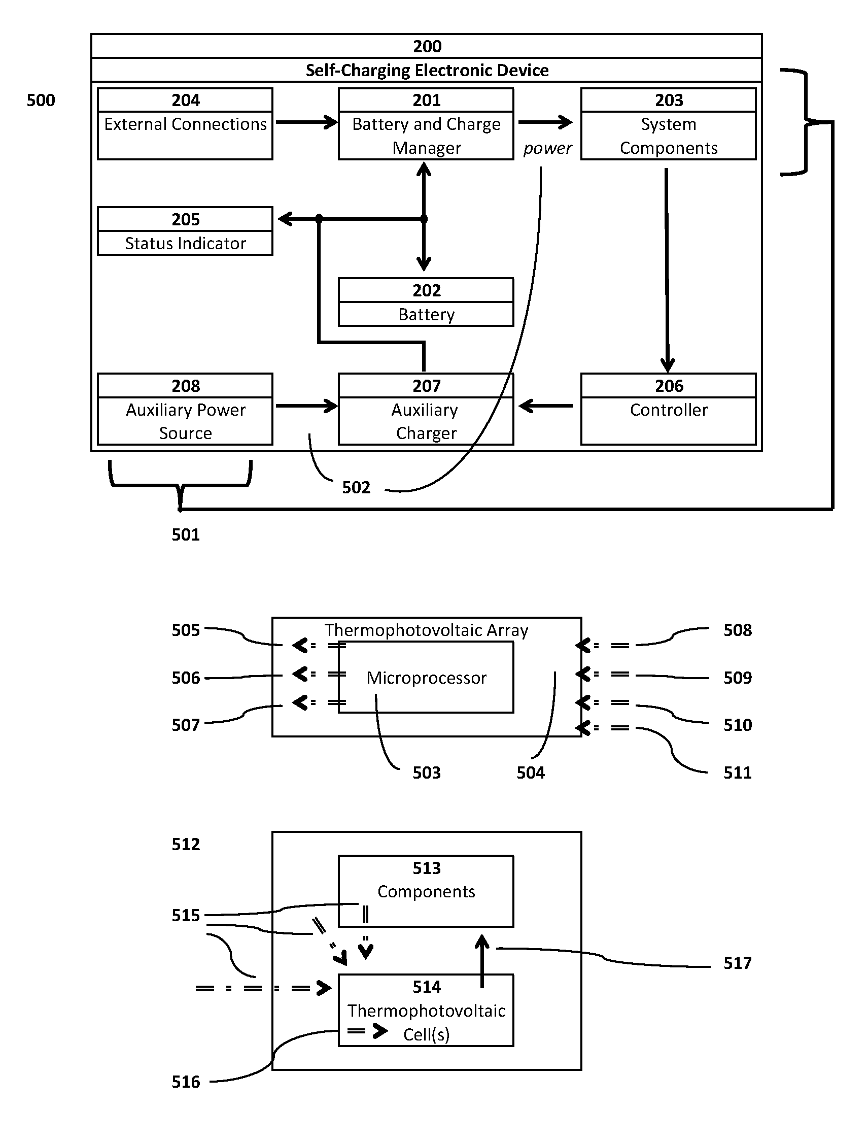
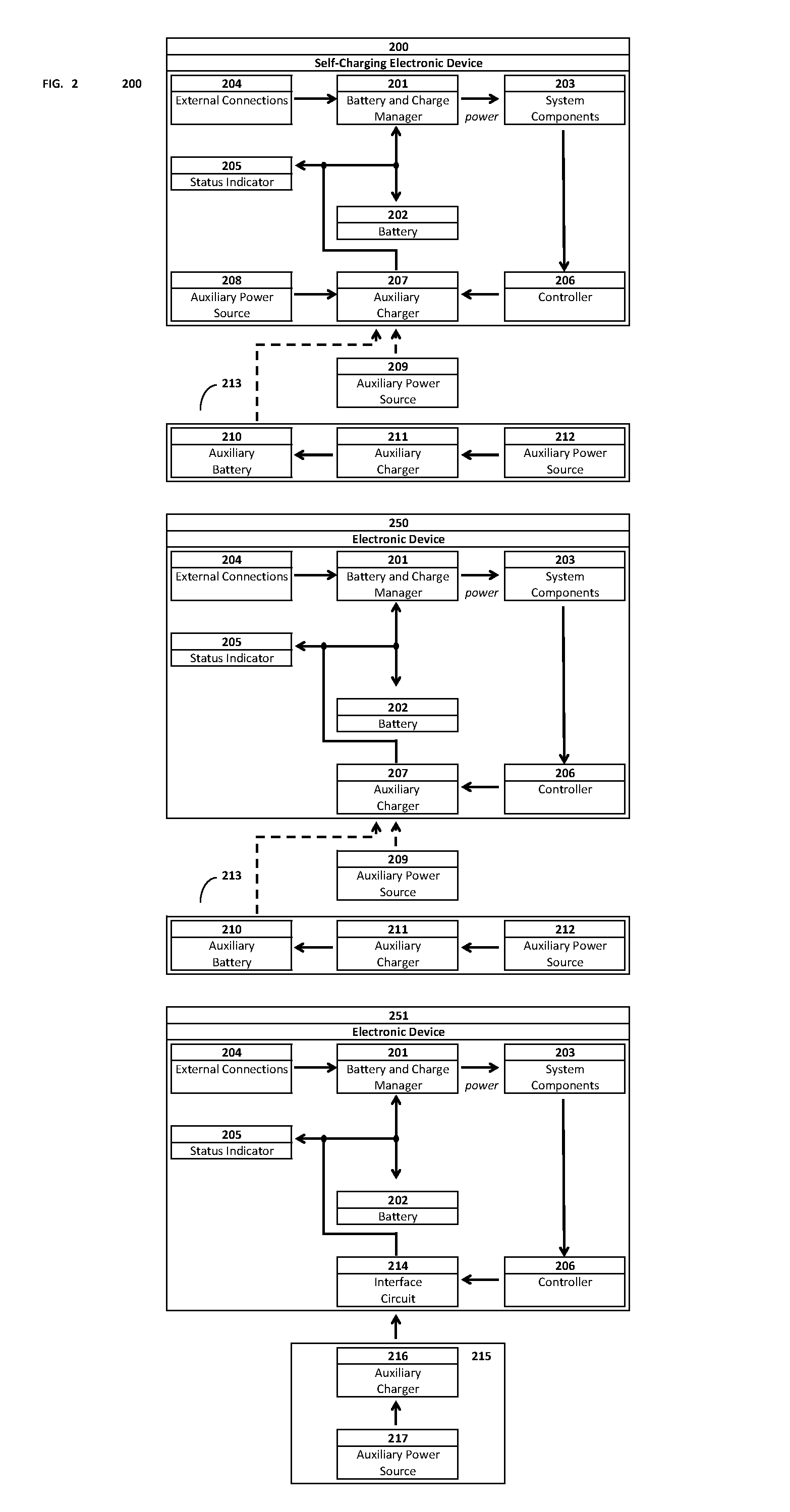
Self-powered portable electronic devices are disclosed that have the capacity to generate their own electrical power, store electrical charge, and distribute electrical power to similarly designed devices in close proximity. Devices generate power in part using one or more non-solar thermal energy sources that have increased stability and efficiency compared to current solar cell powered devices. Devices comprise components including, control processors, data storage, energy storage, dedicated energy and power management processors, and thermophotovoltaic cells that convert thermal energy into electrical power. Devices are capable of transmitting and receiving energy, power, voice and data information using standard frequencies associated with portable devices. Additionally, the invention discloses methods, systems, and apparatuses comprising circuitry that can control power generation from multiple thermophotovoltaic cells and traditional power sources.

Description

CROSS REFERENCE TO RELATED APPLICATION[0001]This application is a continuation in part of U.S. patent application Ser. No. 13 / 590,786 filed Aug. 21, 2012 and claims the benefit of U.S. Provisional Patent Application Nos. 61 / 792,783 filed Mar. 15, 2013 and 61 / 695,485, filed Aug. 31, 2012, the entirety of each is hereby incorporated by reference into this application.BACKGROUND OF THE INVENTION[0002]1. Field of the Invention[0003]The present invention relates to methods, systems, apparatuses, computer readable media, and other means for reliably using thermophotovoltaic cells to power electronic devices.[0004]2. Description of Related Art[0005]Electronic devices are known which are powered by rechargeable batteries such as nickel-cadmium, lithium-ion, nickel-metal hydride, and rechargeable alkaline batteries. The batteries of such devices are often recharged using standard recharging means and methods, such as by plugging a charging cable into the device and into a conventional altern...

Claims


Application Information

Patent Timeline
Patent Type & Authority Applications(United States)
IPC IPC(8): H01L31/04
CPCH01L31/0406H01M10/46H02S10/30H02J7/35H01L31/035218H01L31/035227H02J2207/20Y02E10/50Y02E60/10H01L31/046H02J7/00
Inventor GRIMES, CRAIGKREISLER, KEVIN
Owner PLAIN SIGHT INNOVATIONS LLC
Learn More