Method of Production of a Holographic Sensor

a technology of holographic sensor and holographic sensor, which is applied in the direction of instruments, substrates with holograms, holographic nature/properties, etc., to achieve the effect of reducing the ability of alcohols or other hydrophilic solvents to swell pdms, rapid detection rate and rapid measurement of water conten

Active Publication Date: 2014-04-24
CAMBRIDGE ENTERPRISE LTD
View PDF17 Cites 0 Cited by
  • Summary
  • Abstract
  • Description
  • Claims
  • Application Information

AI Technical Summary

Benefits of technology

[0034]Furthermore, the hologram is immediately visible in daylight or normal room lighting. It is therefore no longer necessary to process the holographic recording material in order to see the hologram, thereby obviating the long, tedious processing steps on the exposed support medium as described above.
[0077]Usually, laser ablation refers to removing material with a pulsed laser, but it is possible to ablate material with a continuous wave laser beam if the laser intensity is high enough and a high speed shutter system is used. For the purposes of the present invention, it is preferable for the laser to be a pulsed laser. A pulsed laser is capable of depositing a much greater energy at a given point on the support medium in as short a time as possible. Laser pulses can vary over a very wide range of duration (milliseconds to femtoseconds) and fluxes, and can be precisely controlled.

Problems solved by technology

The developing process is long and tedious and typically involves the following steps:a) Preparation of the developer and bleach solutions and, optionally, a wetting solution, and setting up appropriate apparatus' for use in the developing process;b) Submersion of the holographic recording plate in the developer solution until the holographic recording plate has turned almost black;c) Rinsing the developer solution from the holographic recording plate, typically using de-ionised water;d) Submersion of the holographic recording plate in the bleach solution until the holographic recording plate is completely clear;e) Rinsing the bleach solution from the holographic recording plate, typically using de-ionized water;f) Optionally, placing the finished hologram in a wetting solution, which helps holograms to turn out much cleaner by reducing streaks and reducing drying time;g) Drying the holographic recording plate.
In contrast, while a wide range of hydrophilic polymeric materials have been found to be suitable in the production of reflection holograms, it has proved exceedingly difficult to successfully introduce holographic reflection gratings into hydrophobic polymeric materials, thus severely limiting the range of applications of reflection of Denisyuk-type reflection holograms.
However, the techniques known to those skilled in the art of production of holographic sensors have not proved successful in introducing a Denisyuk reflection hologram into PDMS.
As noted above, transmission holograms are fundamentally different to reflection holograms and, as is understood by those skilled in the art, techniques used to introduce diffraction gratings into a support medium to produce a transmission hologram are often unsuitable for introducing diffraction gratings into a support medium to produce a reflection hologram.
These transmission holograms produce spurious grating effects of the surface of the support medium which adversely affect the clarity and hence applicability of the Denisyuk hologram.

Method used


Image

  • Method of Production of a Holographic Sensor
  • Method of Production of a Holographic Sensor
  • Method of Production of a Holographic Sensor

Examples


example 1

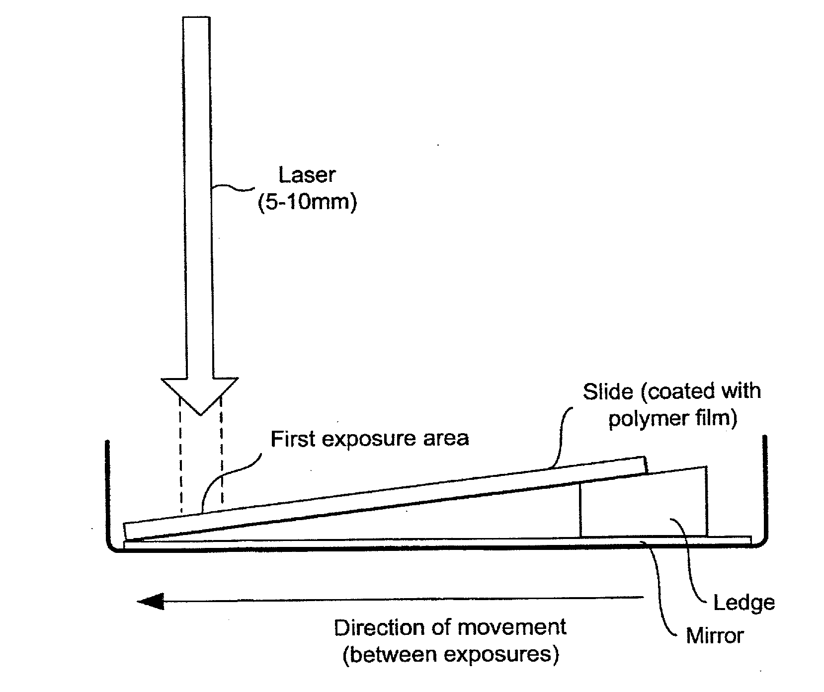
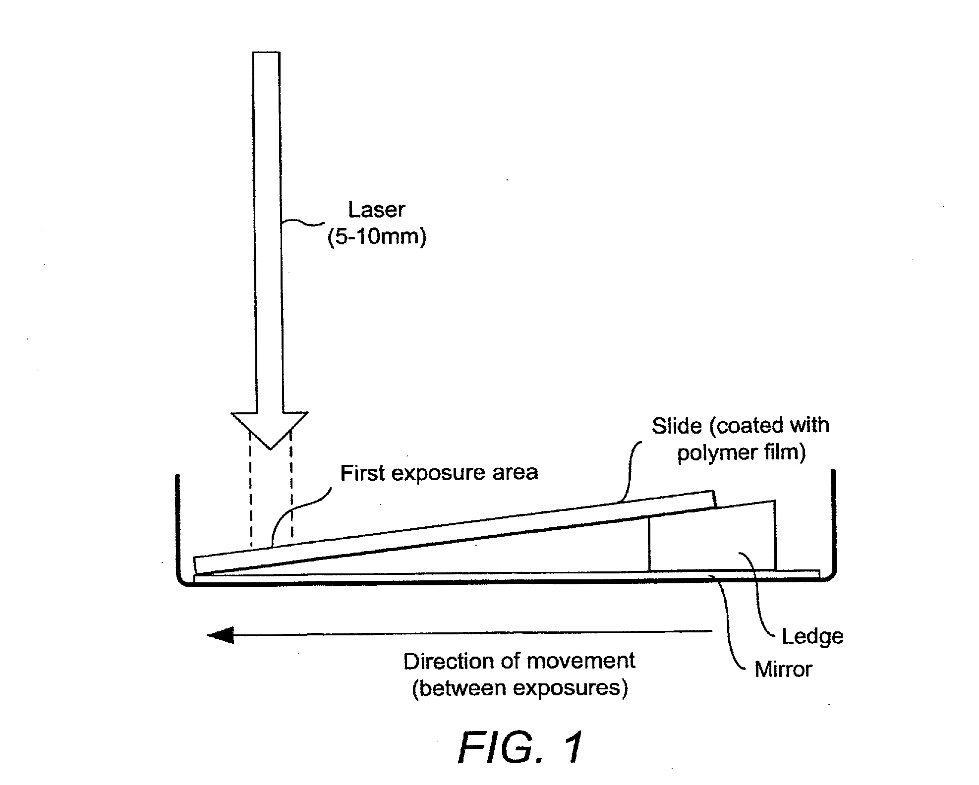
[0186]PDMS solution (Sylgard 184, Dow Corning) was prepared in accordance with the manufacturer's instructions. A ration of 10:1 (w:w) of polymer and hardener were thoroughly mixed at room temperature and allowed to stand for 30 minutes for any air bubbles to dissipate from the solution. The solution was then dispensed in 200 μl aliquots onto clean, glass microscope slides. The solution was spread evenly over the surface of the slides using the side of a pipette tip. The solution on each slide was then cured at 80° C. for 2 hours.

[0187]Alternatively, the slides can be prepared by placing a clean glass surface in position, dispensing the PDMS solution on the upper surface thereof and coating a layer of the solution using the Mayer bar method—the Mayer bar being a road of 1 cm in diameter, close-wound with a 0.2 mm wire. The glass sheet was then cured at 80° C. for 2 hours.

[0188]Next, 200 μl of a 0.1M silver pentafluoropropionate (AgPFP) solution in THF was dispensed onto the cured PD...

example 2

[0196]PDMS coated glass slides were prepared as described in Example 1. 200 μl of a 0.2M solution of hydroquinone in THF was dispensed onto a clean glass surface. The PDMS coated surface of the glass slide was placed on top of the hydroquinone solution of the clean glass surface and allowed to soak the hydroquinone solution for approximately 3 minutes. The slide was then removed and dried in a stream of cool air.

[0197]200 μl of a 0.1M silver pentafluoropropionate solution in THF was dispensed onto a clean glass surface. The PDMS coated surface of the slide was placed on top of the AgPFP solution and allowed to soak the AgPFP solution for approximately 3 minutes. The slide was then removed and dried in a stream of warm air until an amber-brown silver precipitate was visible.

[0198]The slide was exposed to a Nd:YAG frequency doubled laser beam for a period of 6 ns as per Example 1. A segment of the exposed slide was inserted into the twin-cell cuvette as described in Example 1 and chlo...

example 3

[0199]PDMS coated glass slides were prepared as described in Example 1. 200 μl of a 0.2M solution of hydroquinone in THF was mixed with 200 μl of a 0.1M solution of AgPFP in THF and subsequently dispensed onto a clean glass surface. The PDMS coated surface of the glass slide was placed on top of solution on the clean glass surface and the solution was allowed to perfuse into the PDMS film for approximately 3 minutes. The slide was then dried in a stream of warm air and exposed to the beam of laser light as described in Example 1.

[0200]The sensitivity of the holographic reflection grating in the PDMS support medium to hexane vapour and hexane saturated water is illustrated in FIG. 5. The sensitivity of the holographic reflection grating in the PDMS support medium to camping gas (6:4 butane:propane) is illustrated in FIG. 6.


PUM

PropertyMeasurementUnit
grain sizeaaaaaaaaaa
angleaaaaaaaaaa
wavelengthaaaaaaaaaa

Abstract

A method for the production of a holographic sensor which comprises a support medium supporting a reflection hologram wherein the support medium interacts with its physical or chemical environment to create an optical response which is a change in one or more optical properties of the hologram, the method comprising the steps of: a) introducing a colloidal dispersion of a recording material into the support medium; and b) ablating the colloidal particles of the recording material using a pulsed laser to form the holographic element in the support medium. The method of production can be used to introduce a reflection holographic grating into a hydrophobic support medium, in particular, polydimethylsiloxane (PDMS), which possesses an extraordinary ability to swell in the presence of both liquid and / or gaseous low molecular weight hydrocarbons and organic solvents and thus has many applications as a holographic sensor.

Description

CROSS REFERENCE TO A RELATED APPLICATION[0001]This application is a continuation of co-pending application Ser. No. 13 / 122,086, filed Mar. 31, 2011; which is a National Stage Application of International Application Number PCT / GB2009 / 051346, filed Oct. 8, 2009; which claims priority to Great Britain Application No. 0818556.3, filed Oct. 9, 2008; all of which are incorporated herein by reference in their entirety.FIELD OF THE INVENTION[0002]This invention relates to a method of production of a holographic sensor and uses of the sensor produced according to the method.BACKGROUND OF THE INVENTION[0003]A hologram is a recording of an optical interference pattern between light waves. To generate a hologram, two coherent light beams from the one light source—called the object and reference beams—are made to overlap in a photosensitive material such as a photopolymer or silver-halide emulsion. The object beam propagates from the object and thus carries information about it, while the refer...

Claims


Application Information

Patent Timeline
Patent Type & Authority Applications(United States)
IPC IPC(8): G03H1/04
CPCG03H1/0486G03H2001/0044G03H2001/186G03H2001/2231G03H2222/33G03H2270/52G03H1/0005G03H1/0248G03H2260/62G03H1/0465G03H2260/16G03H2240/20G03H2001/0415G03H1/00G03H1/0244
Inventor LOWE, CHRISTOPHER ROBINDAVIDSON, COLIN ALEXANDER BENNETTBLYTH, JEFFREY
Owner CAMBRIDGE ENTERPRISE LTD
Why Eureka
Try Eureka