Passive Imaging Correction System Using Feedback and Method Thereof

a correction system and feedback technology, applied in the field of passive imaging correction system using feedback and method thereof, can solve the problems of several optical distortion effects affecting the propagation of optical waves and signals, and affecting the accuracy of image enhancemen

Inactive Publication Date: 2014-05-08
UNITED STATES GOVERNMENT AS REPRESENTATIVES BY THE SEC OF THE ARMY THE
View PDF1 Cites 25 Cited by
  • Summary
  • Abstract
  • Description
  • Claims
  • Application Information

AI Technical Summary

Benefits of technology

[0016]The present invention is directed to an improved adaptive optics control system utilizing adaptive aperture techniques with or without phase compensation techniques. A preferred embodiment system comprises a variable aperture, such as for example a controllable mirror, placed in an image plane of the system aperture to perform adaptive apodization, a wavefront corrector, and a feedback system based on analysis of image quality to determine updated settings to apply to the apodization mirror and deformable wavefront corrector. The wavefront corrector may comprise a surface controlled by a plurality of actuators, which may be programmed to approximate a sum of weighted Zernike modes selected to approximate the conjugate of the current short-exposure blur deformation to the propagated phase perturbations in the system apodized aperture. Specific settings of the phase map may be governed by a calculation based on a programmed sequence of sub-aperture measurements of phase to produce an estimate of the current atmospheric perturbations affecting a given sub-image frame region of the observed scene. Feedback response may be used to determine the evolution of the current atmospheric state and to adapt the phase correction for different sub-frame regions of the image field of view. The system variable aperture (or apodization) may be separately tuned to reduce the effective number of Zernike perturbation modes that must be tracked by the system. The annular setting of the apodization pattern provides control of both the maximum angular frequency response of the apodized system aperture as well as controlling the number of Zernike perturbation modes necessary to drive the wavefront corrector.
[0018]In an alternative embodiment, the SLM is absent, and the DMD is programmed to only model a variable system aperture, with or without an annular shape. The resulting system will select an optimized effective system aperture diameter based on the current state of turbulence, which is determined by feedback based on image quality. In both embodiments, the image quality for computing the settings of the system aperture apodization is assessed using a sum of squares of image pixel values of a contrast stretched image, which thereby reflects the current level of correction of blur, quantifying the approach of the system-plus-atmospheric modulation transfer function (MTF) toward an optimal setting.
[0019]Alternatively, when computing the sum of squares, the image data can be multiplied by a regional weighting function that focuses on a particular portion of the image field. This method permits the apodization control system to selectively enhance different specific portions of the image that may be at different ranges, experiencing different levels of turbulence-induced blur, thereby permitting the system to either focus on a single area of interest or to progressively scan across the full image field and generate a series of image patches that may be stitched together to produce a complete clear image.
[0020]The preferred method comprises an adaptive system based on a passive analysis of scene content and optimization of the same through the augmentation of the basic optics of a receiver system (lenses, mirrors, and stops) through the introduction of three specific additional elements. The first element is a digital micro-mirror device suitably integrated into the optical path and connected and interfaced to a computer or microprocessor control unit. This element adapts the shape of the wave front that is permitted to pass through the optical train to the final lens and be focused onto the image plane. The second element is a spatial light modulator suitably integrated into the optical path and connected and interfaced to a computer or microprocessor control unit. This element controls the phase of the light across the wave front. The third element is a feedback control circuit designed to test the current state of clarity of the images being produced by the current settings of the optical adjustments of the optical system, to adjust settings on the adaptive optical DMD and SLM elements to obtain sub-aperture sub-frame image sequences, to perform pattern matching of sub-aperture sub-frame images to determine relative angle-of-arrival offsets between different sub-aperture sub-frame images, to compute a conjugate phase model based on measured angle-of-arrival offsets, to apply this conjugate phase correction model to the SLM, to collect full-frame full-apodized aperture images, to supply said full images to an image output channel, and to sequentially control and / or react to user-directed control to select new sub-frame regions of interest on which to focus the feedback control circuit processing. The overall goal is to reduce wave front perturbations through aperture apodization removal of perturbation modes and optimize the wave front conjugation that mitigates the effects of diffraction and turbulent distortions on the propagated object scene.
[0021]In an alternative embodiment, the SLM is absent, and the feedback control circuit is programmed only to optimize the variable system aperture apodization setting for the DMD, with or without an annular shape. The resulting system will select an optimized effective system aperture diameter based on the current state of turbulence, which is determined by feedback based on image quality for a selected sub-frame region. In the embodiments with and without the SLM, the image quality may be assessed as a sum of squares of image pixel values of a contrast stretched image, which thereby reflects the current level of correction of blur, quantifying the approach of the system-plus-atmospheric modulation transfer function toward an optimal setting Alternatively, when using the sum of squares methodology, the sum of squares image data can be multiplied by a regional weighting function that focuses on a particular portion of the image field. This method permits the Zernike tracking system to selectively enhance different specific portions of the image, thereby permitting the system to either focus on a single area of interest or to progressively scan across the full image field and generate a series of image patches that may be stitched together to produce a complete clear image.

Problems solved by technology

Optical signals passing through a time varying inhomogeneous medium, such as the Earth's lower atmosphere, can become significantly distorted when propagating over ranges of even as short as several hundred meters.
In such cases, several optical distortion effects impact propagating optical waves and signals.
Thirdly, point sources separated by angular distances exceeding a characteristic value (the isoplanatic angle) appear to wander independently.
Ground-to-ground imaging-through-turbulence problems essentially involve image blur, which is caused primarily by turbulence close to the system receiving aperture, and image distortion, which is due to turbulence weighted toward the target object that is under observation by the system.
Unfortunately, there are several problems with the use of guide stars.
First, a guide star approach is not a passive solution.
Active systems that require the illumination of a target scene prior to detection of significant targets are not stealthy and are undesirable in most tactical situations that are of interest in a military situation.
Second, many imaged objects may not have useful reflective properties that will work properly with an illumination beacon.
Other alternatives, such as placing an illuminator in the object plane, requiring objects of interest to mount glint reflectors, or forming laser-induced fluorescence (LIF) guide stars on target surfaces are obviously not practical from an Army application standpoint.
Another difficulty with the guide star approach is that the coherent propagating wave from a guide star is affected by turbulent scintillation, which is most strongly weighted at the center of the optical path, not at the system receiver.
Thus the guide star method is not optimized to produce a useful result for removing turbulent blur.
First, the turbulence that is causing the most image blur is close to the sensing aperture.
Second, scene elements that are separated in the scene by a significant angular separation experience anisoplanatic effects limiting the ability of a system to correct turbulent image perturbations at large angular separation from the guide star.
This effect impairs the performance of guide-star-based systems, because turbulent perturbations on the guide star wavefront in one part of the image frame are not the same turbulent perturbations that impact scene elements in another part of the image frame.
Guide-star-based systems thus do not do well at correcting for turbulent blur in different parts of an imaged scene, underscoring the need for a passive method that can correct for turbulence sequentially in different parts of the image.
In particular, source points present on surfaces that are rough on the order of a single wavelength of the propagating radiation, will not produce a single coherent source even in a point source sense.
Unfortunately, for many terrestrial (ground-to-ground) imaging scenarios the probability of obtaining any portion of an image that is free of significant turbulence may be so small as to provide a negligible chance of obtaining a set of null-turbulence patches sufficient to construct an unperturbed image.
A 24:139-155 (2007)] present at the system aperture gives rise to a problem.
That problem is a limitation on how frequently a given mode may be corrected given a specific rate of image collection by the optical system, in combination with the strength of aberration due to a specific mode.
The limitation of this approach is the high number of image samples to be collected rapidly enough (several thousand sample images per second) to track the evolving state of the various perturbation modes.
This is because the method is relatively inefficient, relying on a stochastic adjustment procedure.
Because the maximum sampling rate of an image at an adequate signal-to-noise ratio is limited by the amount of ambient light available to produce the image and the system's light gathering capability, sufficiently high frame rates may not be possible without the augmentation of the system by a high intensity light source in the imaged scene to provide the necessary illumination.
This amenity may not be available in military or in many other contexts.

Method used


Image

  • Passive Imaging Correction System Using Feedback and Method Thereof
  • Passive Imaging Correction System Using Feedback and Method Thereof
  • Passive Imaging Correction System Using Feedback and Method Thereof

Examples


Embodiment Construction

[0067]The embodiments herein and the various features and advantageous details thereof are explained more fully with reference to the non-limiting embodiments that are illustrated in the accompanying drawings and detailed in the following description. Descriptions of well-known components and processing techniques are omitted so as to not unnecessarily obscure the embodiments herein. The examples used herein are intended merely to facilitate an understanding of ways in which the embodiments herein may be practiced and to further enable those of skill in the art to practice the embodiments herein. Accordingly, the examples should not be construed as limiting the scope of the embodiments herein.

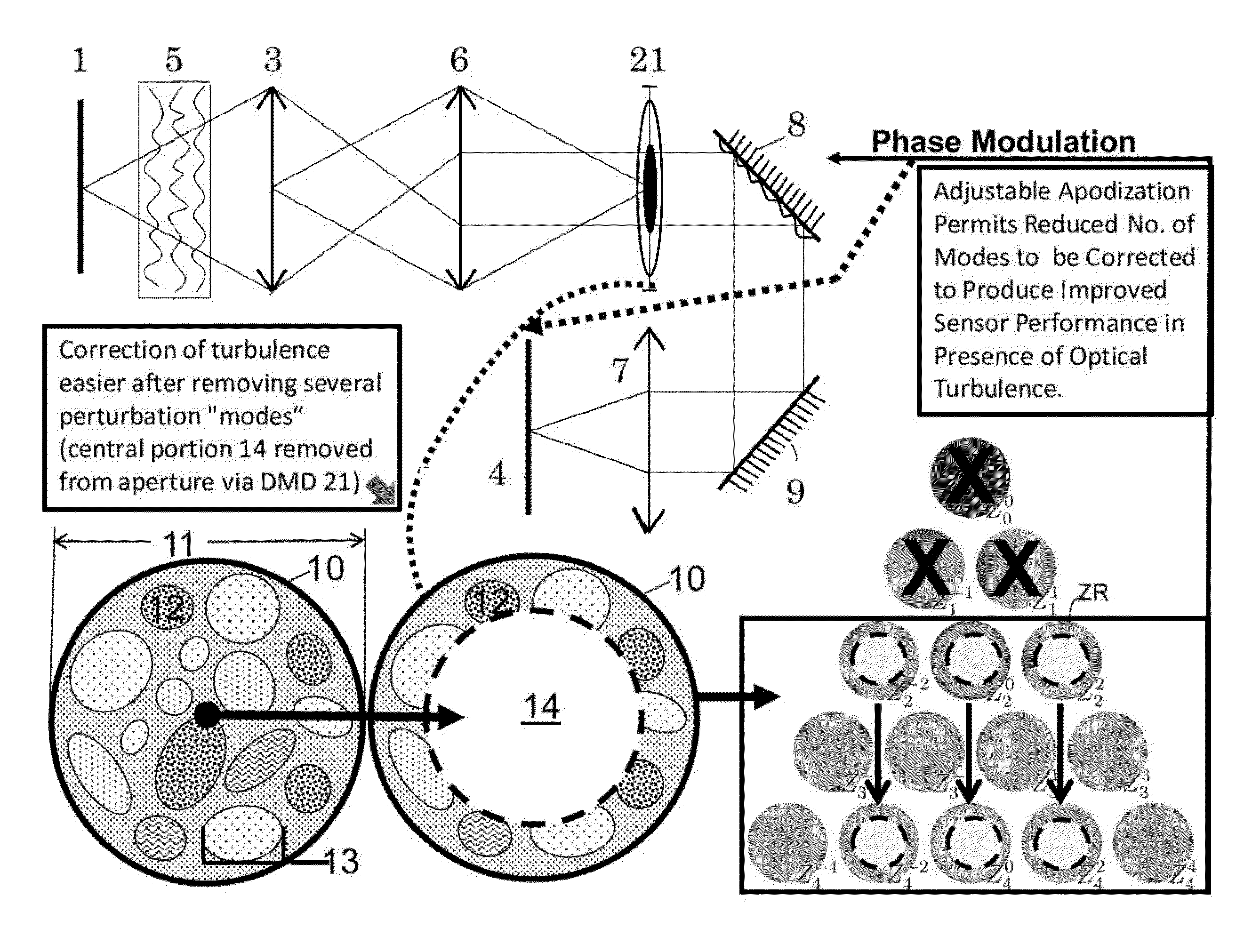
[0068]The methodology of a preferred embodiment does not utilize any randomized search procedure, nor does it utilize any form of specialized emitting source in the object plane. Rather, a systematic search technique is proposed, in combination with an adaptive aperture control system, permitti...


PUM


Abstract

A method and system for image processing comprising an opening for entrance of light for forming an image by the system; at least one optical element through which the light passes; a variable aperture operatively associated with the at least one optical element placed in the optical train at an image plane and comprising a plurality of settings comprising first mask settings for shielding portions of the light and second mask settings for selectively masking portions of the light that pass through the first mask settings; an imager, the at least one processor being operatively connected to the variable aperture and imager for controlling the passage of the light through the variable aperture by selecting one of plurality of first mask settings and associated second mask settings, obtaining image results using the settings, comparing image results obtained by the respective mask settings, and determining the optimal first mask setting.

Description

STATEMENT OF GOVERNMENT INTEREST[0001]The embodiments herein may be manufactured, used, and / or licensed by or for the United States Government without the payment of royalties thereon.BACKGROUND OF THE INVENTION[0002]The present invention is directed to, inter alia, passive correction of turbulence affected incoherent imaging using an optical system (and methodology) for, inter alia, reducing the effects of short-exposure blur due to atmospheric optical turbulence.[0003]Optical signals passing through a time varying inhomogeneous medium, such as the Earth's lower atmosphere, can become significantly distorted when propagating over ranges of even as short as several hundred meters. The primary mechanism of this distortion is due to temperature fluctuations driven by heating and cooling of the air which is most severe at the Earth's surface. In such cases, several optical distortion effects impact propagating optical waves and signals. Coherent propagation is significantly affected by...

Claims


Application Information

Patent Timeline
Patent Type & Authority Applications(United States)
IPC IPC(8): H04N5/235
CPCH04N5/2351G02B26/06H04N23/75H04N25/60G03B7/085G02B26/00G06T5/001
Inventor TOFSTED, DAVID M.O'BRIEN, SEAN GERARD
Owner UNITED STATES GOVERNMENT AS REPRESENTATIVES BY THE SEC OF THE ARMY THE
Why Eureka
Try Eureka