Coatings, composition and method related to non-spalling low density hardface coatings

a low-density hard-face coating, non-splashing technology, applied in the direction of coatings, vacuum evaporation coatings, transportation and packaging, etc., can solve the problems of thermally sprayed tungsten carbide-cobalt coatings, for example, are very hard, brittle and dense, and ceramics generally decompose instead of melting

Active Publication Date: 2014-05-15
HYBRID MATERIALS LLC
View PDF6 Cites 3 Cited by
  • Summary
  • Abstract
  • Description
  • Claims
  • Application Information

AI Technical Summary

Benefits of technology

[0013]The present invention has been developed in response to the current state of the art, and in particular, in response to these and other problems and needs that have not been fully or completely solved by currently available expedients. Thus, it is an overall object of the present invention to effe

Problems solved by technology

Hardface coatings, particularly chromium and tungsten based coatings formed by the thermal spraying of composite powders are well known, but they are generally prone to spalling, and they are heavy.
Thermally sprayed tungsten carbide-cobalt coatings, for example, are very hard, brittle and dense.
The formation of coatings by thermal spraying ceramics such as ceramic nitrides had been proposed, but ceramics generally decompose instead of melting.
Thermal spraying operations are typically carried out at temperatures well in excess of 1900 degrees centigrade, so attempts to form coatings by thermal spraying ceramic nitrides had generally been unsuccessful.
The application of ceramic nitrides via physical vapor deposition and chemical vapor deposition operations for forming coatings that control wear and friction had been previously proposed, but such vapor deposition operations tended to be slow and expensive.
Previous attempts to improve wear had typically involved making harder and stiffer coatings at the expense of ductility.
In general, as the coatings beca

Method used


Image

  • Coatings, composition and method related to non-spalling low density hardface coatings
  • Coatings, composition and method related to non-spalling low density hardface coatings
  • Coatings, composition and method related to non-spalling low density hardface coatings

Examples


example 1

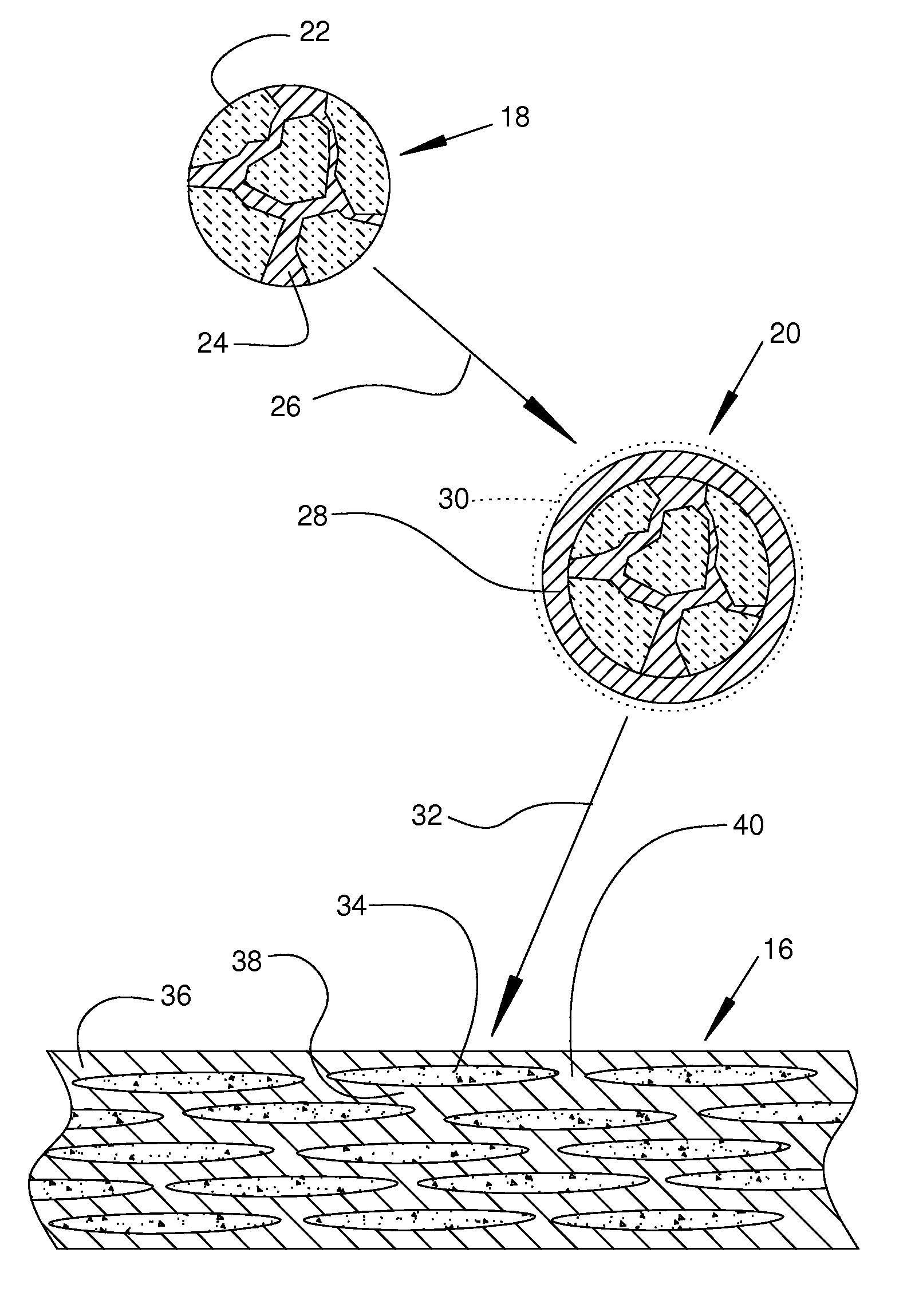
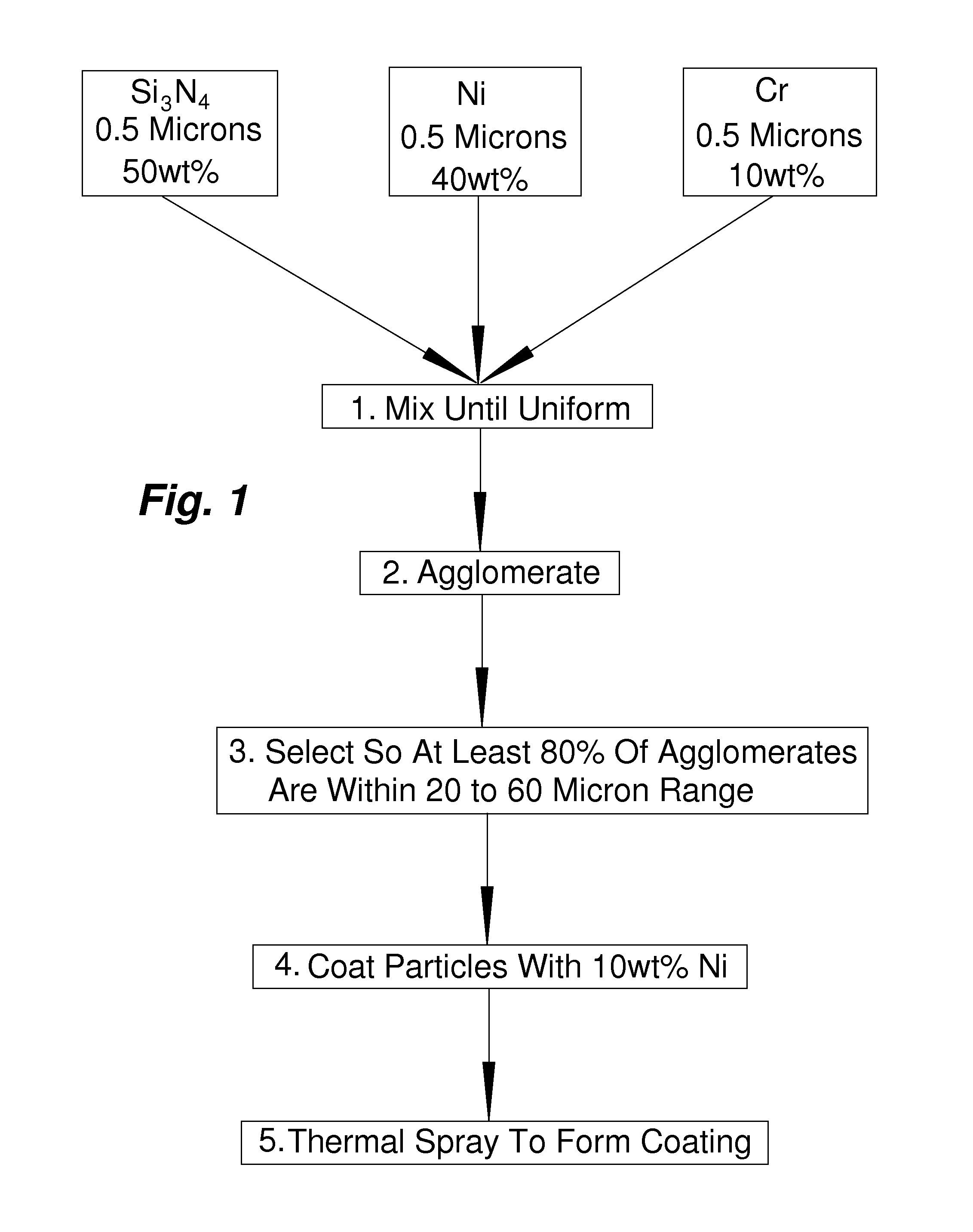
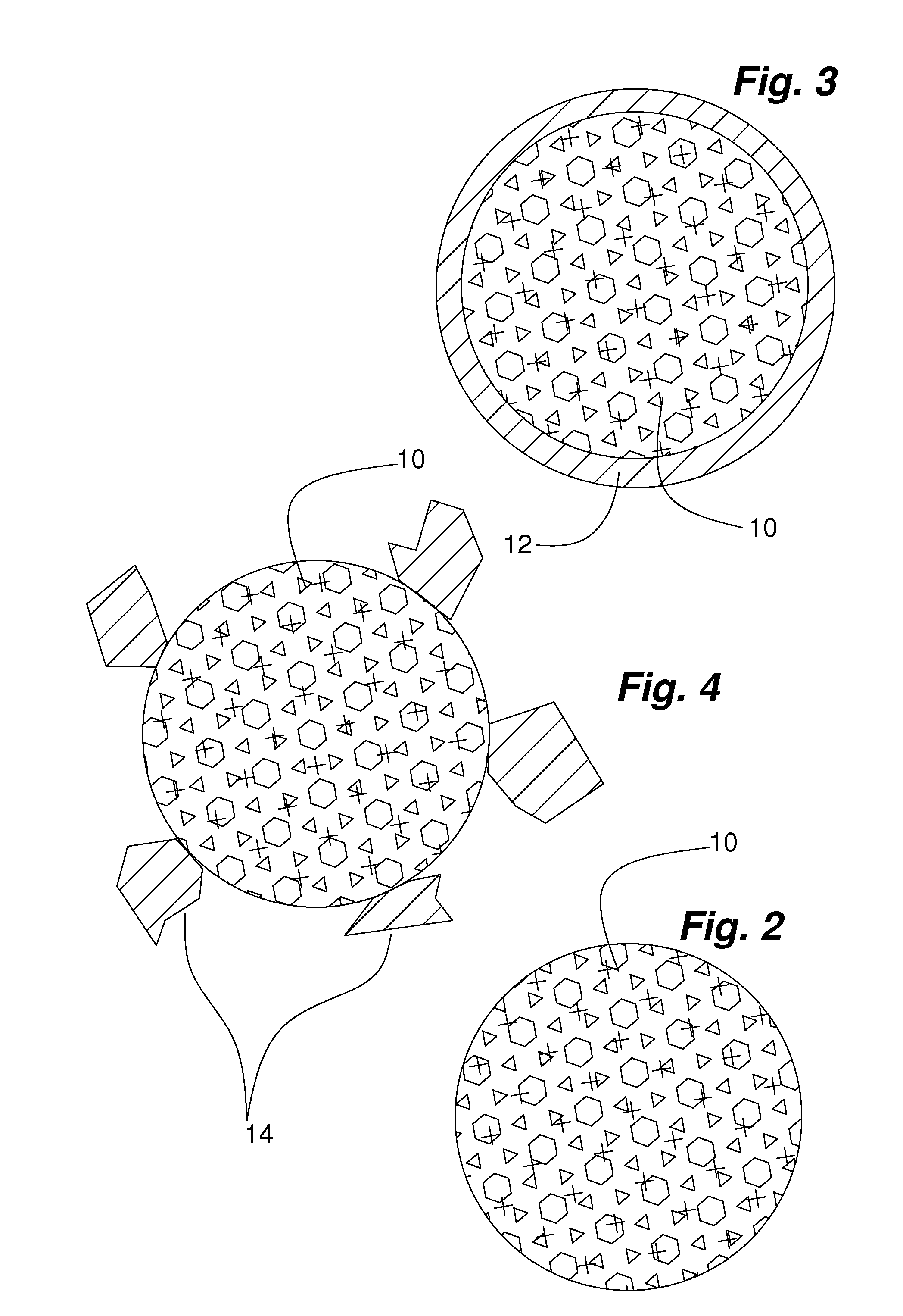
[0039]The first of two agglomerated microcomposite powders were prepared by ball milling about 0.5 micron Si3N4 powders with about 28 volume percent (V %) Ni and about 7V % Cr powder for about 24 hours in a ball mill. This Example is diagrammatically illustrated in FIG. 1. The second powder consisted of about 0.5 micron TiN powder with about 28 V % Ni and about 7 V % Cr, and it was prepared in the same way as the Si3N4—Ni—Cr powders. All of the following steps were identical for both powders. A polyvinyl alcohol binder was added along with water and conventional surfactants to reduce the viscosity of the resulting slurry to between 100 and 300 centipoises. An agglomerated powder was formed by spray drying the slurry. The slurry was spray dried at about 15,000 revolutions per minute using a centrifugal atomizer, a gas temperature of about 300 degrees Centigrade, and an exit temperature of about 180 degrees Centigrade to create approximately spherical, free flowing agglomerated powder...


PUM

PropertyMeasurementUnit
Lengthaaaaaaaaaa
Lengthaaaaaaaaaa
Lengthaaaaaaaaaa

Abstract

A heterogeneous composite body that is spall resistant and comprises a substantially discontinuous cermet phase in a substantially continuous metal rich matrix phase. The heterogeneous composite body is typically bonded to a substrate to form a hardfacing on the substrate. The heterogeneous composite body exhibits ductile phase toughening with a strain to failure of at least about 2 percent, a modulus of elasticity of less than about 35 million pounds per square inch, and a density of less than about 7 grams per cubic centimeter. The metal rich matrix phase between the ceramic rich regions in the heterogeneous composite body has an average minimum span of about 0.5 to 8 microns to allow ductility in the heterogeneous composite body. The heterogeneous composite body has a Vicker's hardness number of greater than approximately 500. The ceramic rich regions exhibit high hardness as compared with the matrix phase.

Description

RELATED APPLICATIONS[0001]This application is a continuation-in-part of U.S. patent application Ser. No. 12 / 699,779, filed Feb. 3, 2010, which claims the benefit of U.S. Provisional Application No. 61 / 149,680, filed Feb. 3, 2009.GOVERNMENT INTEREST[0002]This invention was made with government support under contract #EPA EP-D-06-053, microcomposite coatings for chrome replacement, awarded by Environmental Protection Agency at 1025 F St, Washington D.C., and subcontract #USAF-0040-SC-0024-1 under GDIT prime contract #FA8601-04-F-0040, awarded by the United States Air Force at Oklahoma City, Okla.BACKGROUND OF THE INVENTION[0003]1. Field of the Invention[0004]The invention relates in general to hardface coatings, compositions and methods, and, more particularly, embodiments of the present invention relate to hardface coatings, compositions, and methods that relate to spall resistant, low density hardface coatings.[0005]2. Description of the Prior Art[0006]Hardface coatings, particularl...

Claims


Application Information

Patent Timeline
IPC IPC(8): C09D1/00
CPCC09D1/00C23C14/223B22F7/08C22C29/00C22C29/02C23C4/067Y10T428/12486
Inventor SHERMAN, ANDREWGLASGOW, CURT
Owner HYBRID MATERIALS LLC
Why Eureka
Try Eureka