

Ammonia oxidation catalyst
- Summary
- Abstract
- Description
- Claims
- Application Information
AI Technical Summary
Benefits of technology
Problems solved by technology
Method used
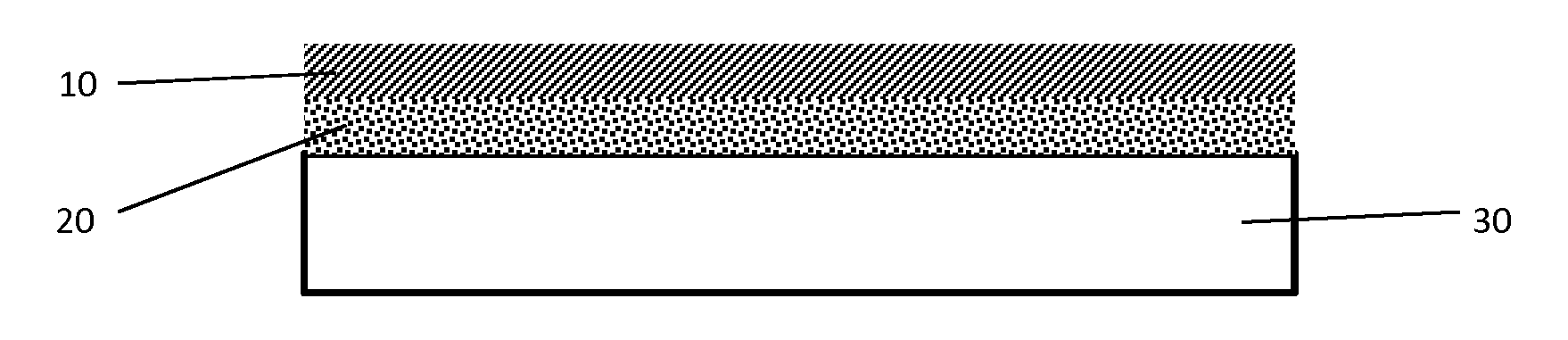
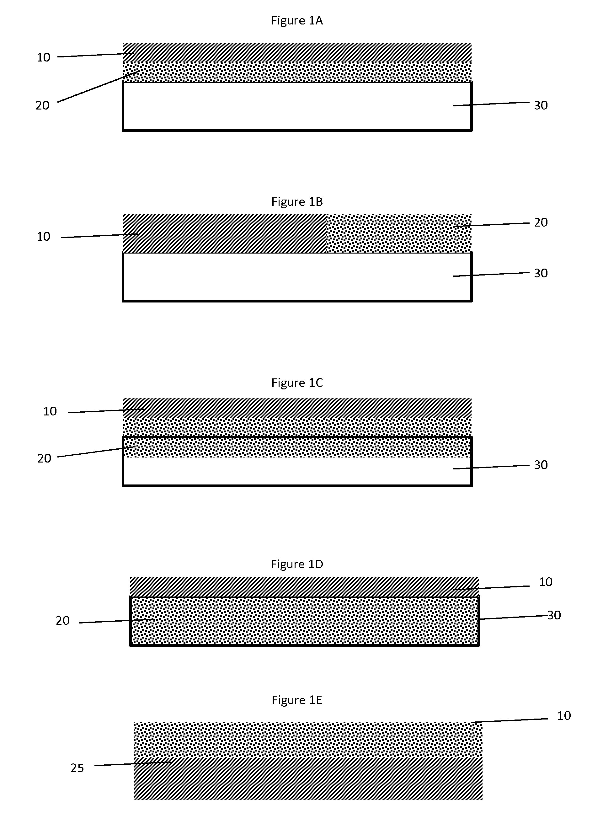
Image

Examples
example 1
Catalyst Preparation
[0052]A first catalyst layer was prepared as follows: Deionized water and alumina washcoat having a d50 of about 3.4-4.2 μm were mixed in a container using a high shear mixer. Succinic acid was slowly added to achieve a concentration of about 100 g / ft3 and the admixture was continuously stirred for at least 30 minutes. Palladium nitrate was added and the resulting admixture was stirred for an additional 60 minutes. Natrasol™ was added and the resulting slurry was mixed for 24 hours. The final washcoat was applied to a 200 cpsi cordierite substrate, dried, and then calcined at 500° C.
[0053]A second catalyst layer was prepared as follows: A titania source was heated to about 500° C. for about 1 hour and then added to dissolved ammonium metatungstate to incipient impregnate tungsten on the titania. The resulting material was dried to form a powder which was dried and calcined. The calcined TiO2 / W powder was impregnated with diluted vanadia and the resulting material...
example 2
NH3 Conversion Performance
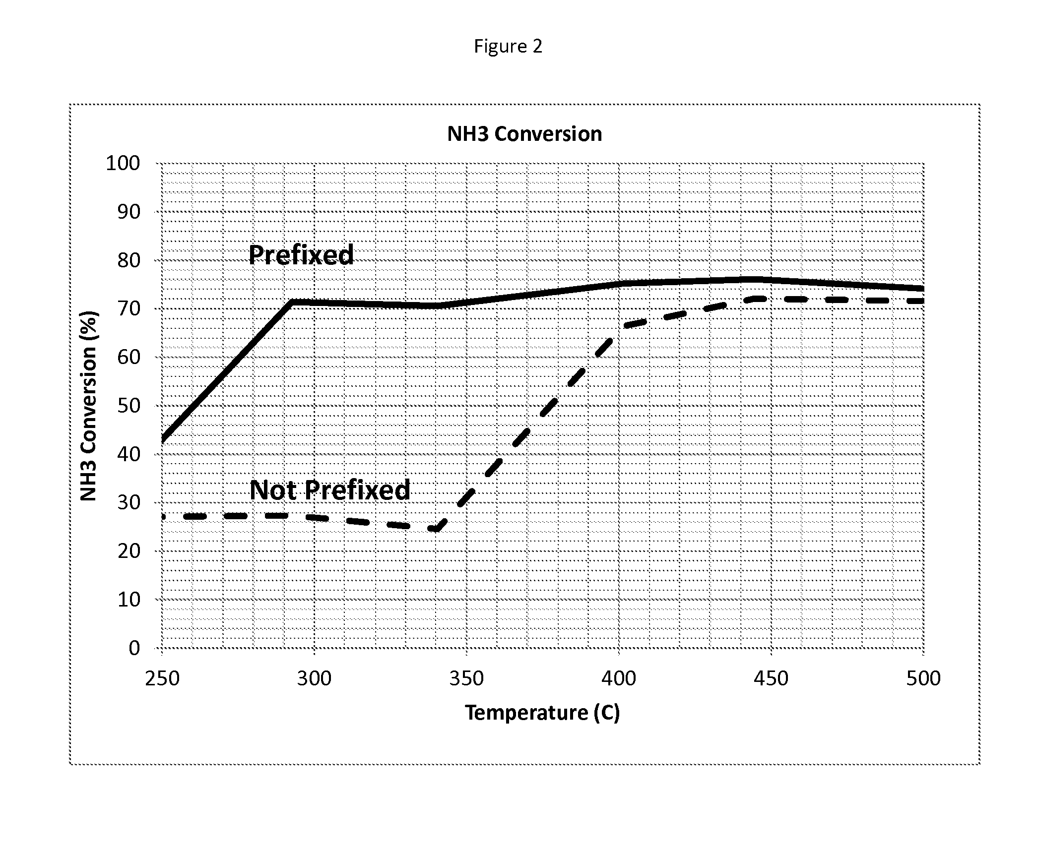
[0054]The NH3 conversion performance of a catalyst prepared according to Example 1 was compared to a similar catalyst article, but without prefixed vanadia.
[0055]The comparative sample was prepared as follows: A first catalyst layer was prepared as follows: Deionized water and alumina washcoat having a d50 of about 3.4-4.2 μm were mixed in a container using a high shear mixer. Succinic acid was slowly added to achieve a concentration of about 100 g / ft3 and the admixture was continuously stirred for at least 30 minutes. Palladium nitrate was added and the resulting admixture was stirred for an additional 60 minutes. Natrasol™ was added and the resulting slurry was mixed for 24 hours. The final washcoat was applied to a 200 cpsi cordierite substrate, dried, and then calcined at 500° C.
[0056]A second layer was prepared as follows: Deionized water was mixed with titania and Ludox®. The material was aged for at least 24 hours. The material had a d50 of 90 of <10...
example 3
NOx Selectivity Performance
[0059]The NOx selectivity performance of a catalyst prepared according to Example 1 was compared to a similar catalyst, but without prefixed vanadia under the same test conditions described in Example 2.
[0060]The results of these tests are provided in FIG. 3. Here, the catalyst containing prefixed vanadia showed similar NOx conversion compared to the catalyst that did not have prefixed vanadia.
PUM
| Property | Measurement | Unit |
|---|---|---|
| Temperature | aaaaa | aaaaa |
| Time | aaaaa | aaaaa |
| Percent by mass | aaaaa | aaaaa |
Abstract
Description
Claims
Application Information