Passively controlled smart microjet cooling array

Active Publication Date: 2014-07-24
PARKER INTANGIBLES LLC
View PDF13 Cites 40 Cited by
  • Summary
  • Abstract
  • Description
  • Claims
  • Application Information

AI Technical Summary

Benefits of technology

[0011]The construction of the orifice or jet nozzle is such that the nozzle is closed below a certain threshold temperature T0. As the electric component or PCB below a specific nozzle heats up, heat is transferred through the conductive pins onto the orifice/injector plate and then into or directly into the nozzle material. As the nozzle material or parts of it heat up beyond the T0 threshold value, the jet nozzle or parts of it deform allowing for fluid to be ejected or discharged from the nozzle with fluid being replenished behind the nozzle through one or more fluid feed channels. As a consequence of the impinging fluid jet, the electronic component(s) and/or PCB portion below the specific nozzle cools down, reducing the heat transfer through the thermally conductive pins. In view of the cooling effect of the impinging cooling fluid, the heat transfer through the conductive pins is reduced or even reversed resulting in the localized nozzle temperature to fall back below the threshold temperature T0. This results in closure of the previously opened nozzle until the electronic component(s) or PCB portion below the nozzle heats up again until the prescribed threshold value T0 is reached again. Response time will depend on and can be controlled via the thermal resistance path between the deforming nozzle or nozzle elements and the component surface to be cooled; and the threshold temperature T0 relates to a specific component surface temperature Ts which is being controlled by the specific cooling nozz

Problems solved by technology

Timed activation has proven deficient, however, as being insufficiently related to actual temperature conditions.
Active control systems, however, by employing so

Method used


Image

  • Passively controlled smart microjet cooling array
  • Passively controlled smart microjet cooling array
  • Passively controlled smart microjet cooling array

Examples


Example

[0031]Embodiments of the present invention will now be described with reference to the drawings, wherein like reference numerals are used to refer to like elements throughout. It will be understood that the figures are not necessarily to scale.

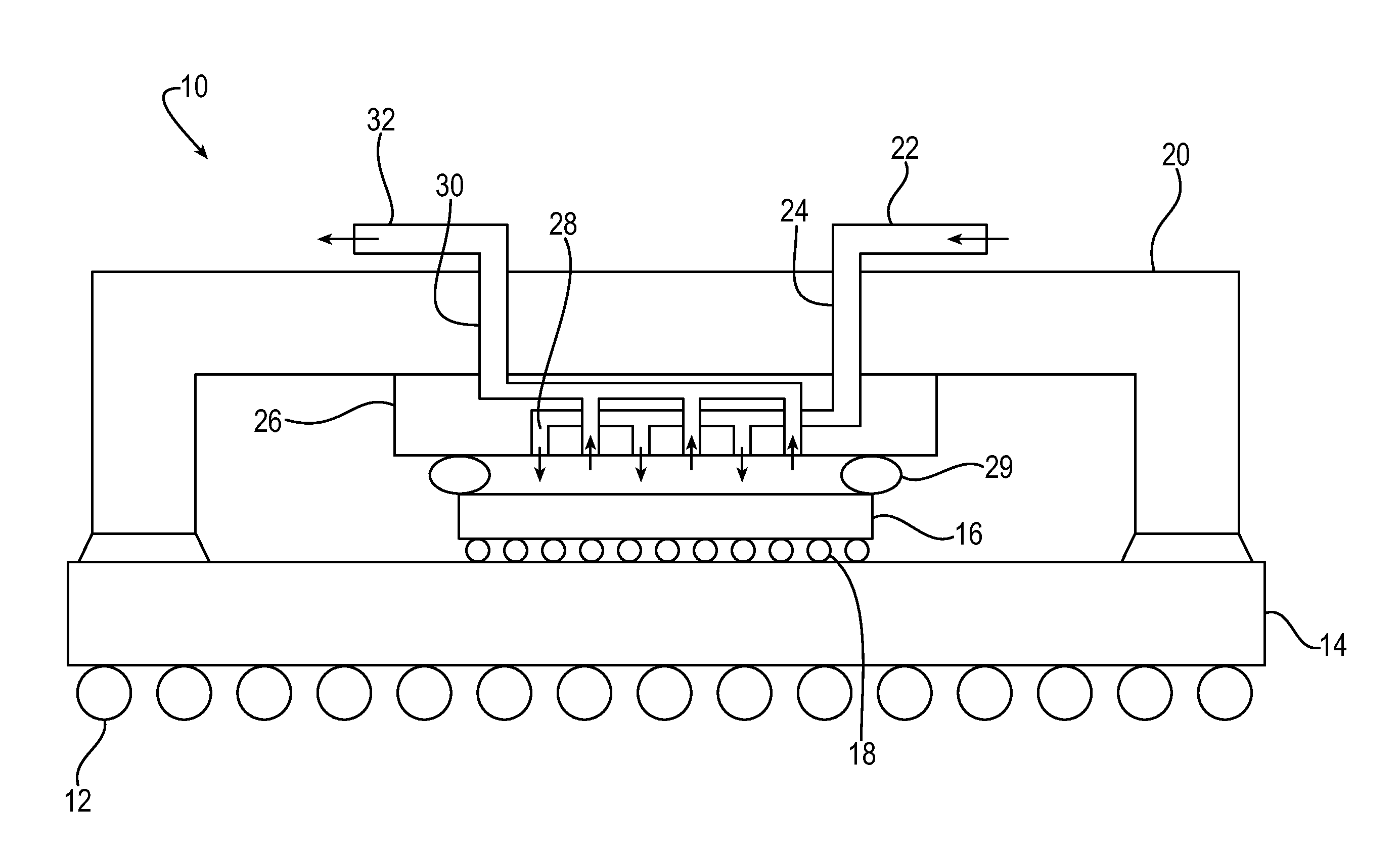
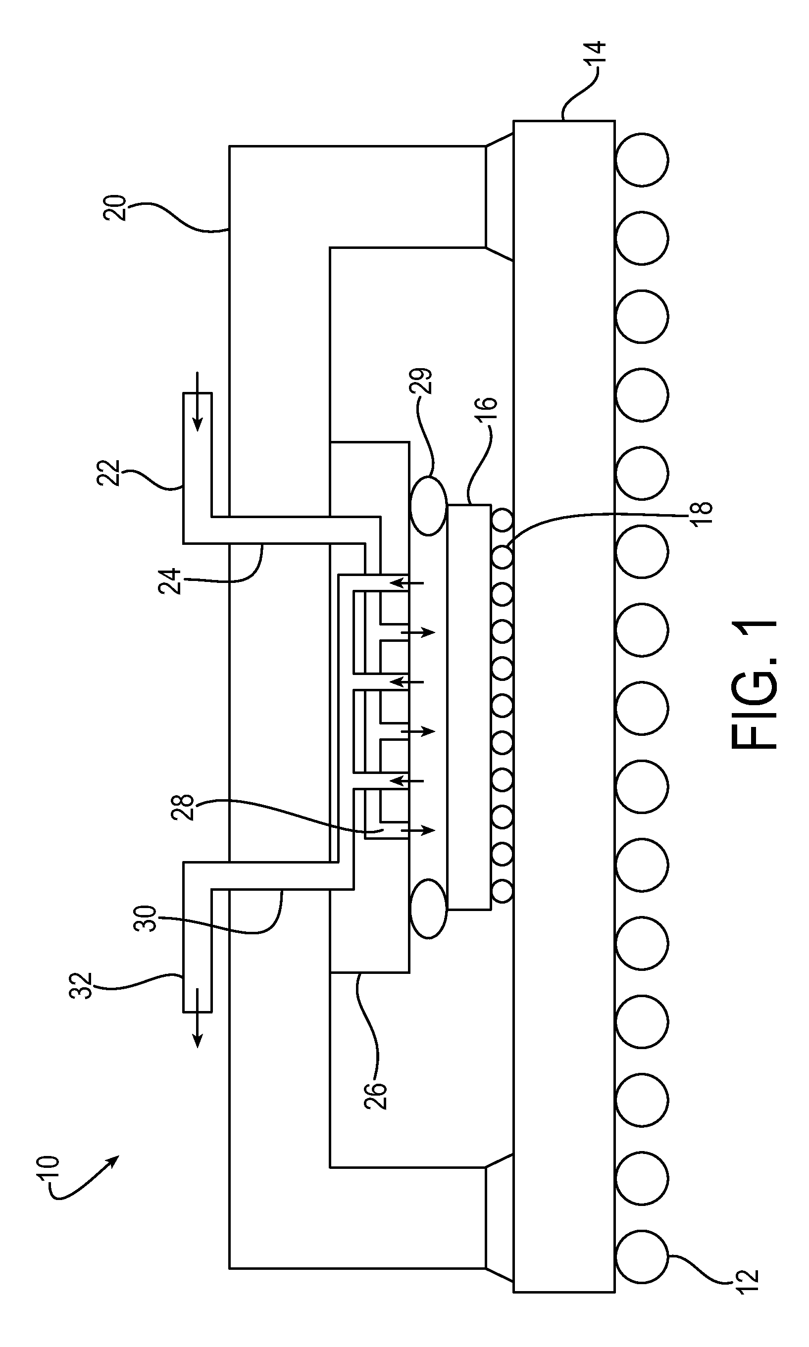
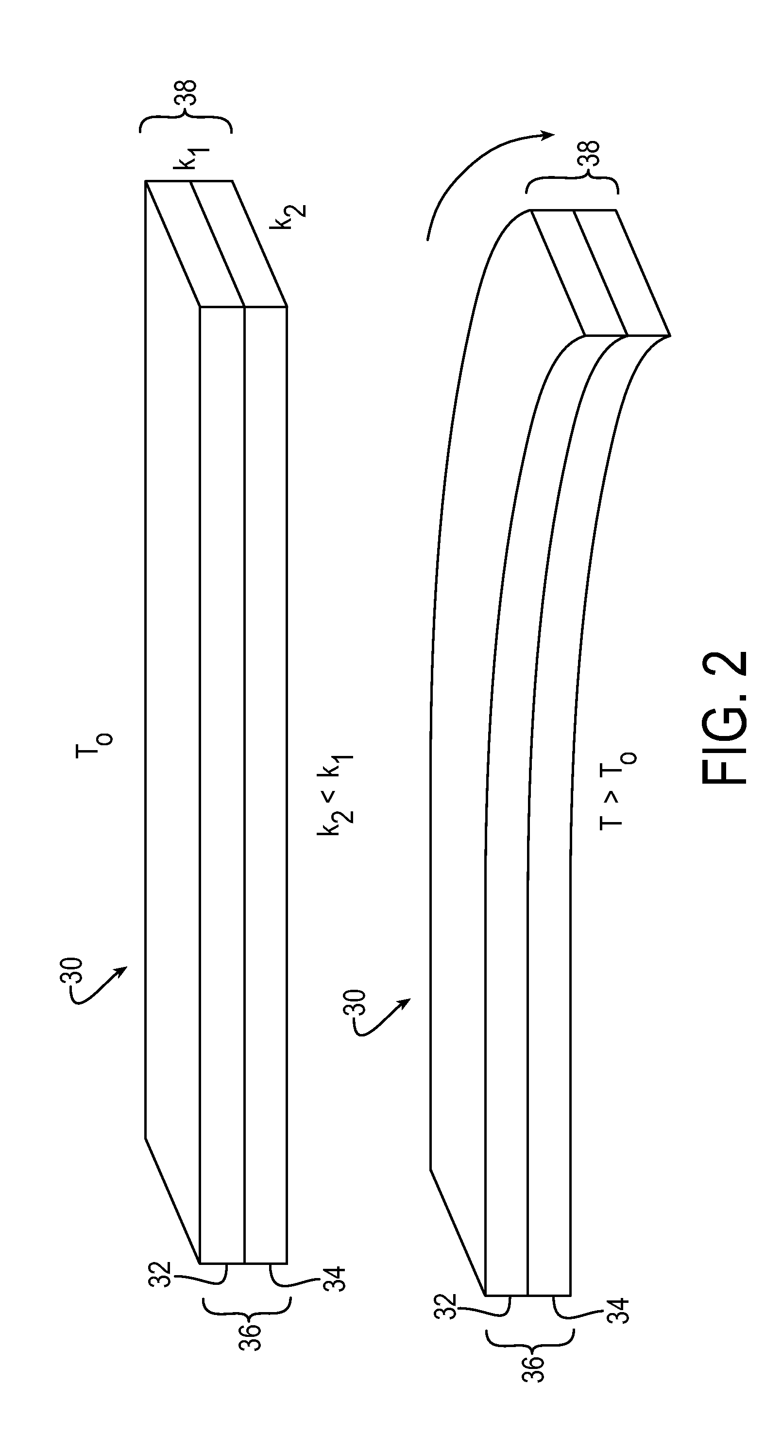
[0032]The passive nature of the described impingement cooling system is based in part on the nature of the thermal expansion of certain materials, which can result in deformation of the material as temperature changes. In exemplary embodiments, two different materials having different thermal expansions are adhered together as a bi-material strip. For example, the bi-material strip may be a bimetallic strip of two different metallic or polymer materials adhered to each other or otherwise fused together. Exemplary bimetallic materials that are known in the art include strips of brass and invar, steel and copper or steel and brass joined together by riveting, brazing or welding. Other thermostatic bimetals products are available commercially, e....


PUM


Abstract

An impingement cooling system for cooling electronic components includes a nozzle array having a plurality of nozzles in fluid communication with a source of cooling fluid, each nozzle including a deflection structure that deforms above a threshold temperature. A plurality of thermally conductive pins respectively are in thermal contact with the deflection structures and conduct heat from at least one of the electronic components to the deflection structures. When a heated nozzle within the nozzle array reaches a temperature above the threshold temperature due to heat conducted from the respective thermally conductive pin, the deflection structure of the heated nozzle deforms from a closed position to an open position to permit cooling fluid to impinge upon the electronic component. The deflection structure may be a deflection plate formed of a bimetallic material having layers of different thermal expansion coefficients, or a thermally responsive two-way shape memory material.

Description

FIELD OF THE INVENTION[0001]The present invention relates to impingement cooling arrays for electronic components, particularly electronic components fixed to an electronics circuit board, and more particularly to a passively controlled smart microjet impingement cooling array for cooling such electronic components.BACKGROUND OF THE INVENTION[0002]Cooling of electronics components can be achieved by impinging gas or liquid onto such components via gas jets, or mixed liquid / gas flows (i.e., liquid sprays in a surrounding gas phase). FIG. 1 is a schematic diagram that depicts a conventional cooling jet system for cooling electronic components, referenced collectively as the electronics system 10.[0003]The electronics system 10 includes a plurality of electrical contacts 12 connecting a chip carrier circuit board 14 onto which electronic components may be fixed. An exemplary electronic chip 16 has its own set of electrical contacts 18 that plug into or are connected to the circuit boar...

Claims


Application Information

Patent Timeline
IPC IPC(8): H05K7/20
CPCH05K7/2089H05K7/20281H01L23/4735H05K7/20136H05K7/20345H01L2224/16225H01L2924/0002H01L2924/15311H01L2924/16152H05K7/20H01L2924/00
Inventor MEHRING, CARSTEN
Owner PARKER INTANGIBLES LLC
Why Eureka
Try Eureka