Optoelectronic devices with thin barrier films with crystalline characteristics that are conformally coated onto complex surfaces to provide protection against moisture
- Summary
- Abstract
- Description
- Claims
- Application Information
AI Technical Summary
Benefits of technology
Problems solved by technology
Method used
Image
Examples
example 1
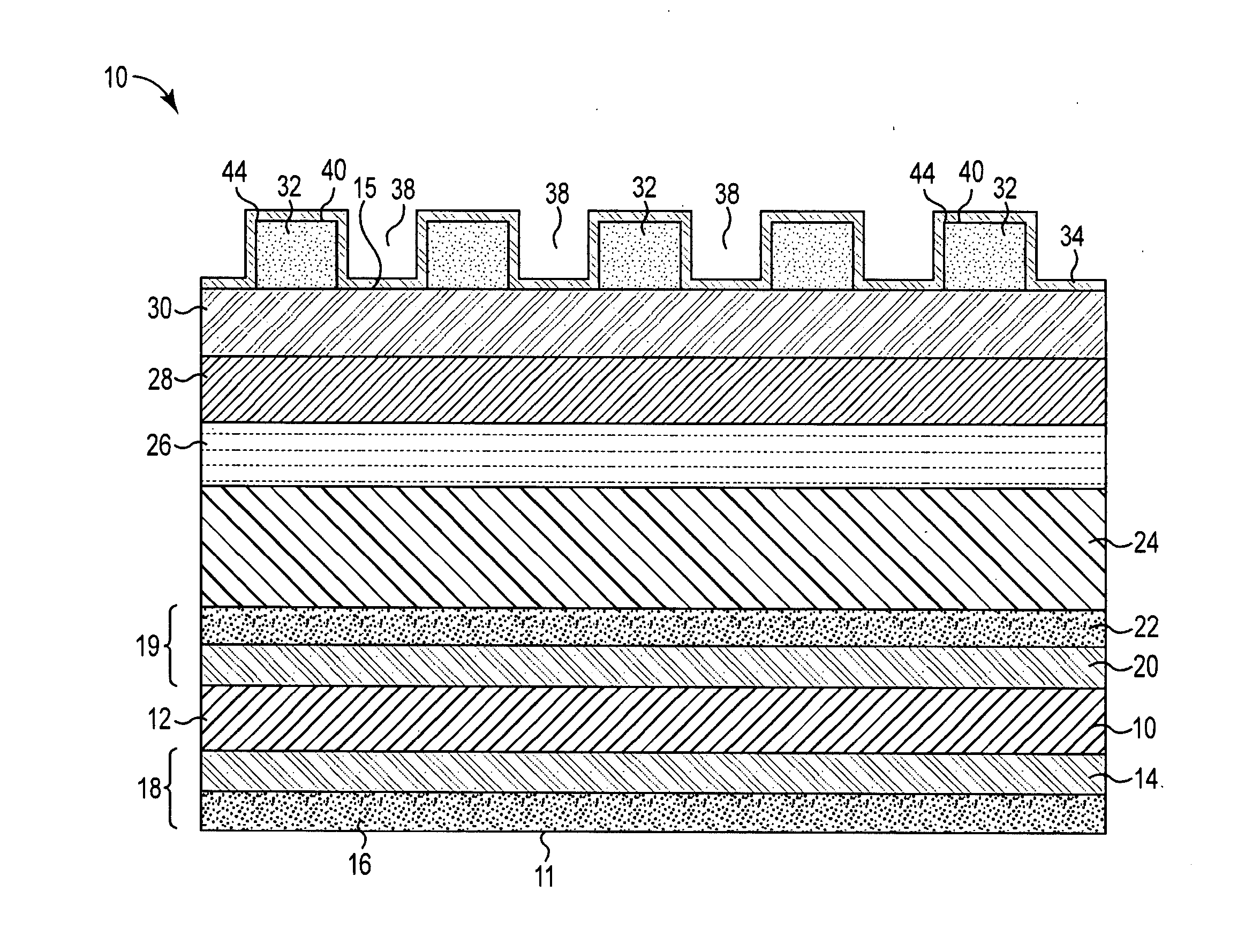
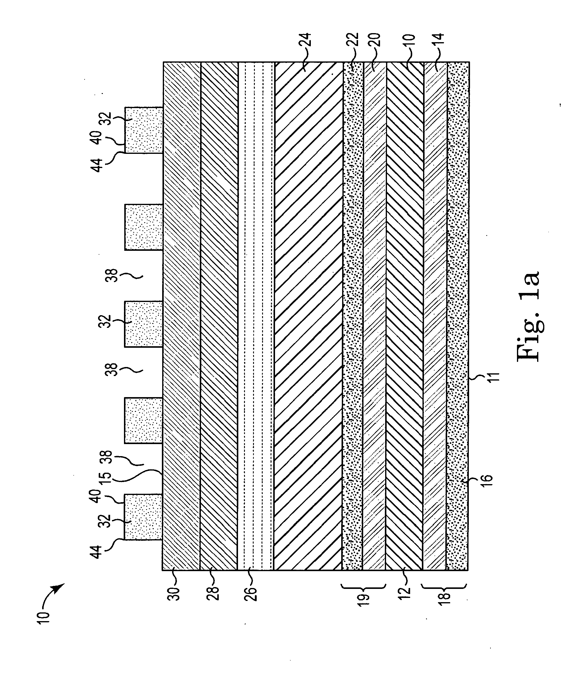
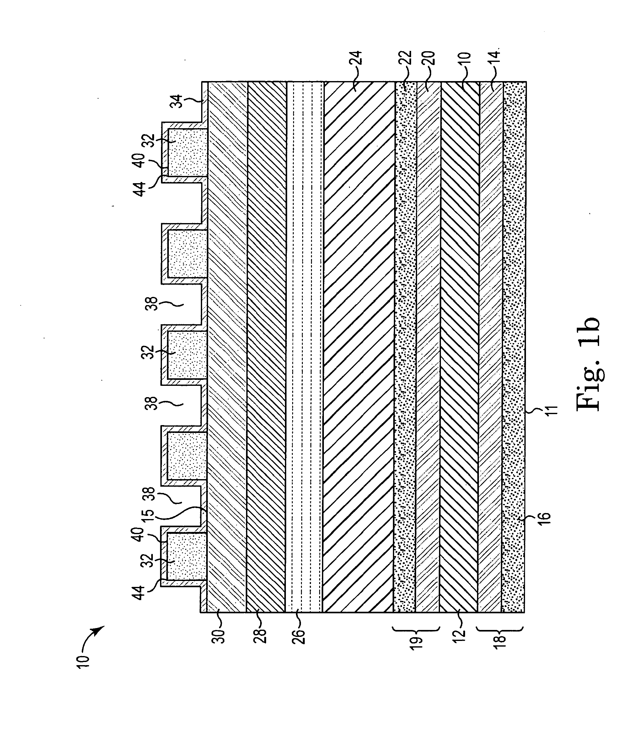
[0097]CIGS solar cells having the structure shown in FIG. 1a were fabricated. Support 12 was a stainless steel foil. Layers 14 and 16 were formed from Cr and Mo respectively. Backside contact region 18 included Cr layer 14 and molybdenum layer 16. Absorber region 24 was formed from CIGS material by co-evaporation of Cu, In, Ga, and Se and was approximately 2 μm thick. Following, 40 nm thick CdS was deposited on the CIGS film as buffer region 26 through chemical bath deposition. A 50 nm thick insulating layer of ZnO as window layer 28 and a 150 nm thick transparent conducting oxide layer of indium tin oxide (ITO) as layer 30 were deposited on the CdS by RF magnetron sputtering. Contact to the ITO was made with an evaporated Ni / Ag grid pattern as grid 32 that is connected to a thicker bus bar (not shown) at the edge of the foil 12 for electrical contact.
[0098]Transmission electron microscopy (TEM) analysis was conducted using an FEI Tecnai F-30 microscope with a Schottky field-emissio...
example 2
[0101]Both sets of samples prepared in Example 1 were subject to damp heat testing to assess the ability of the barrier films to protect the cells against moisture. The damp heat tests were conducted in a temperature and humidity controlled chamber at 85° C. and 85% relative humidity. The solar cells were taken out from the test chamber every 24 hours and their current-voltage characteristics were measured. The control solar cells were tested under damp-heat conditions for 168 hours, while the SnO2-film-coated cells were tested under identical conditions for 240 hours. The current-voltage characteristics of the solar cells were recorded periodically under 100 mW / cm2 (AM 1.5) illumination generated by a solar simulator equipped with a Xe-arc lamp. The fill factor (FF), the open circuit voltage (Voc), the short circuit current density (Jsc), and the cell efficiency (represented by the symbol η and given by the expression η=FF·Jsc·Voc) were measured outside the damp-heat test chamber u...
example 3
[0102]This example reports the data obtained in Example 2 for the first set of sample solar cells for which the SnO2 films were deposited on completed solar cells having a structure according to FIG. 1b. FIGS. 2a and 2b show the results from the first set of experiments. The SnO2 films were deposited under twelve different sputtering conditions reported in the Figures.
[0103]FIG. 2(a) shows the efficiency of the solar cells, normalized to their initial efficiency, after 144 and 216 hours of damp-heat testing. FIG. 2(b) shows the absolute values of the efficiencies after 144 and 216 hours in the damp-heat testing chamber. The results are also compared with the unprotected CIGS solar cells, named as “Control” in FIGS. 2(a) and 2(b).
[0104]The data show that SnO2 films help increase the damp-heat durability of the CIGS solar cells. A significant fraction of the SnO2-coated cells performed better than the control samples after 216 hours in the damp-heat test chamber.
[0105]Additionally, th...
PUM
 Abstract
Description
Claims
Application Information
 - R&D
- Intellectual Property
- Life Sciences
- Materials
- Tech Scout
- Unparalleled Data Quality
- Higher Quality Content
- 60% Fewer Hallucinations
Browse by: Latest US Patents, China's latest patents, Technical Efficacy Thesaurus, Application Domain, Technology Topic, Popular Technical Reports.
© 2025 PatSnap. All rights reserved.Legal|Privacy policy|Modern Slavery Act Transparency Statement|Sitemap|About US| Contact US: help@patsnap.com


