Welded steel pipe with excellent welded heat-affected zone toughness and process for producing same

a technology of welded steel pipe and heat-affected zone, which is applied in the direction of pipes, blade accessories, machines/engines, etc., can solve the problems of increased man-hours, significant productivity reduction, and difficulty in feasibility of this technique, and achieve excellent welded heat-affected zone toughness, low cost, and high productivity.

Inactive Publication Date: 2014-08-14
JFE STEEL CORP
View PDF0 Cites 3 Cited by
  • Summary
  • Abstract
  • Description
  • Claims
  • Application Information

AI Technical Summary

Benefits of technology

[0035]According to the present invention, a welded steel pipe, having excellent welded heat-affected zone toughness, for line pipes can be manufactured with high productivity at low cost. This is highly effective for industrial purposes.

Problems solved by technology

However, increasing the number of layers for butt welding as disclosed in Patent Literatures 1 and 2 and grinding a tack-welded portion as disclosed in Patent Literatures 3 and 4 both cause an increase in man-hour, leading to a problem with a significant reduction in productivity.
In order to achieve the reduction in welding speed of the tack weld or a tack weld metal with high toughness, it is necessary to select a combination of welding materials; hence, the feasibility of this technique is difficult.
Standards, such as API (American Petroleum Institute) standards, applied to line pipes specify that seam welding needs to be performed such that no tack weld is left and therefore these techniques cannot be used to manufacture products meeting the standards.
However, the application of the object to a heavy-walled material requires an increase in welding heat input.
It is difficult to obtain a desired heat-affected zone having a high-toughness microstructure.
However, it is difficult for this method to ensure the toughness of an ICCGHAZ formed by two-run welding because sufficient toughness is not achieved only by the reduction in the welding heat input.

Method used


Image

  • Welded steel pipe with excellent welded heat-affected zone toughness and process for producing same
  • Welded steel pipe with excellent welded heat-affected zone toughness and process for producing same

Examples


examples

[0104]Slabs containing chemical compositions shown in Table 1 were reheated and were hot-rolled, followed by accelerated cooling, whereby steel plates were manufactured.

TABLE 1Chemical compositions (unit: mass percent)ComponentNo.CSiMnPAlCuNiCrMoNbVTiCaMgREMA0.0390.081.560.0040.0300.280.280.150.180.0220.0050.0100.0025——B0.0680.021.650.0120.026—0.230.200.100.012—0.011—0.0010—C0.0540.181.640.0070.0240.200.39—0.120.0100.0080.006——0.0090D0.0500.102.050.0110.035———0.120.036—0.0200.0015——E0.0580.151.800.0080.002—0.280.20—0.025—0.009———F0.0580.101.650.0170.0260.280.18—0.200.0250.0110.0100.0010——G0.0540.251.750.0040.0240.250.25—0.100.024—0.0130.0015——H0.0710.181.090.0040.0260.350.350.300.200.0210.0050.0110.0022——I0.0650.061.560.0030.0260.100.350.150.150.028—————ComponentAc1Ac3No.ZrNCeqPMA(° C.)(° C.)A—0.00450.4031.35728891B—0.00430.4182.61730874C—0.00300.3924.35721885D0.00200.00600.4164.11732887E—0.00350.4173.48735873F—0.00390.4065.46727886G—0.00400.3995.79726887H—0.00400.4006.65735887I—0.0...


PUM

PropertyMeasurementUnit
grain sizeaaaaaaaaaa
diameteraaaaaaaaaa
toughnessaaaaaaaaaa

Abstract

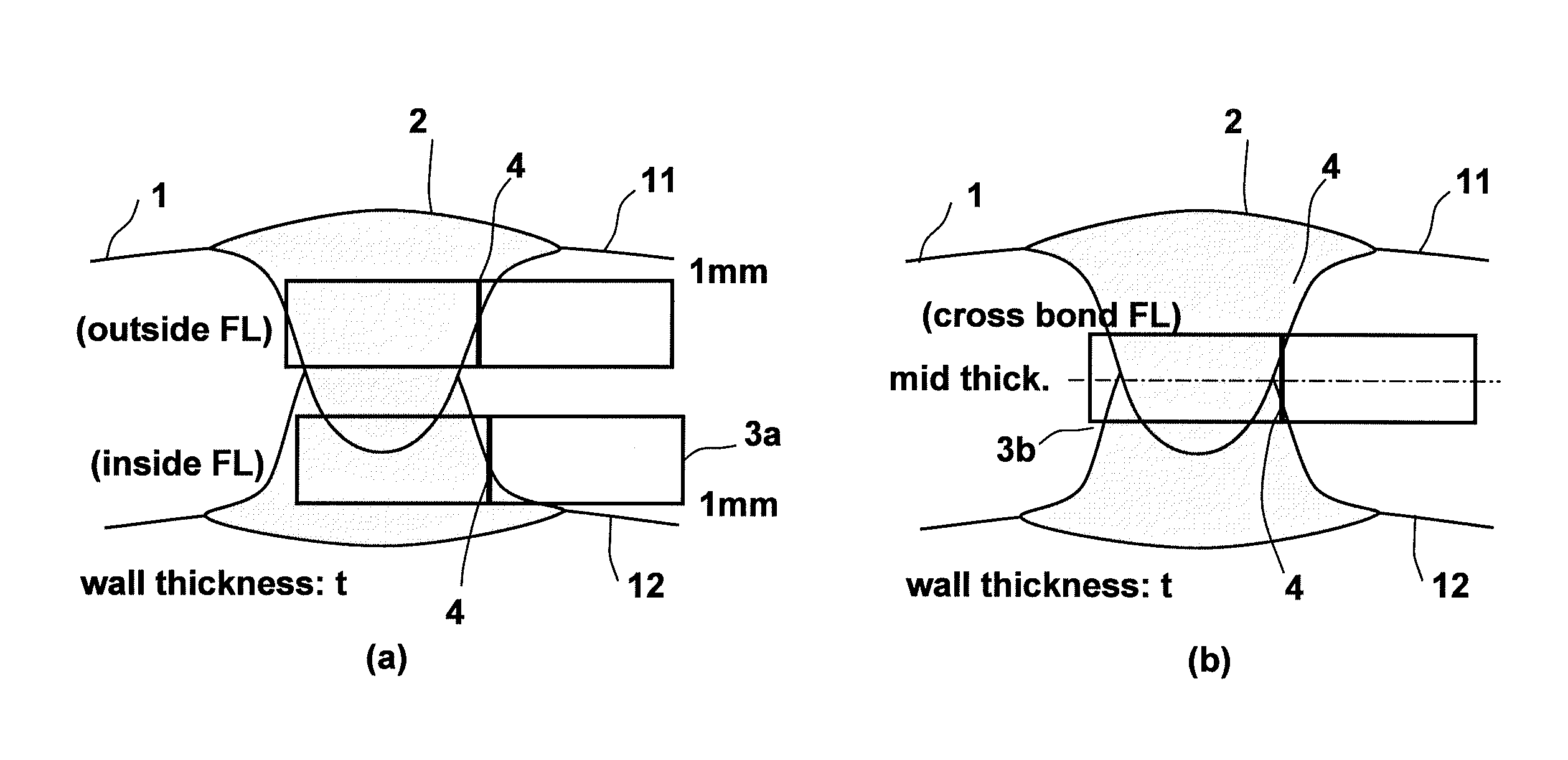
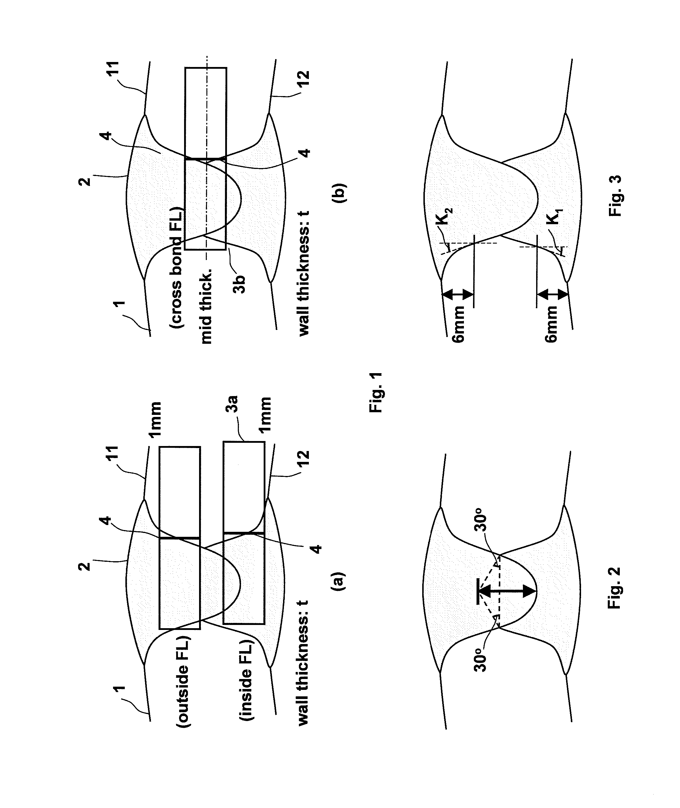
A welded steel pipe with excellent welded heat-affected zone toughness includes a butt weld formed by prior welding either an inner surface or an outer surface with a single layer for each of the inner and outer surfaces, wherein in the metallographic structure of a welded heat-affected zone, the martensite-austenite constituent (MA) area fraction is 4% or less, the average prior-austenite grain size is 400 μm or less, and the following items are taken into account: the average prior-austenite grain size of a welded heat-affected zone formed by prior welding, the average prior-austenite grain size of a welded heat-affected zone formed by subsequent welding, the bead width determined at a position 5 mm apart from the tip of a weld bead formed by subsequent welding, the fusion line tilt angle of a weld bead of prior welding, and the fusion line tilt angle of a weld bead of subsequent welding.

Description

FIELD OF THE INVENTION[0001]The present invention relates to a welded steel pipe which is manufactured in such a way that a steel plate is formed into a cylinder by cold bending and abutting surfaces thereof are welded, which is suitable as a line pipe for natural gas or crude oil, and which has excellent welded heat-affected zone toughness.BACKGROUND OF THE INVENTION[0002]High-strength, heavy-walled line pipes have been increasingly used to transport natural gas or crude oil year by year for the purpose of achieving an increase in transportation efficiency by high pressure operation. In sub-sea pipeline systems for transporting natural gas, more heavy-walled line pipes are required with an increase in laying depth from the viewpoint of ensuring buckling resistance during laying, water pressure strength during operation, and safety against currents.[0003]On the other hand, in the case of using line pipes laid on the seabed at high pressure, gas is adiabatically depressurized during ...

Claims


Application Information

Patent Timeline
Patent Type & Authority Applications(United States)
IPC IPC(8): F16L9/02B23K9/00
CPCB23K9/0026F16L9/02B23K9/0282B23K9/18C21D9/50C22C38/001C22C38/002C22C38/02C22C38/04C22C38/06C22C38/08C22C38/12C22C38/14C22C38/16C22C38/18C22C38/42C22C38/44C22C38/46C22C38/48C22C38/50C22C38/58C21D2211/001C21D2211/008C21D8/105C21D8/10C22C38/005B23K9/0253B23K33/006B23K2101/10B23K2103/04Y10T428/12292
Inventor TANIZAWA, AKIHIKOOTA, YOSHIAKIUCHITOMI, NORIAKIOKATSU, MITSUHIRONISHIMURA, KIMIHIRO
Owner JFE STEEL CORP
Why Eureka
Try Eureka