Output over-voltage protection circuit for power factor correction

a protection circuit and power factor technology, applied in the direction of emergency protective arrangements for limiting excess voltage/current, energy industry, arrangements responsive to excess voltage, etc., can solve the problem of serious distortion of outputted current waveform, power loss, and low power factor of switching mode power supply, so as to improve system stability and reliability, simplify circuits, and no cost increase

Active Publication Date: 2014-09-18
CSMC TECH FAB2 CO LTD
View PDF3 Cites 8 Cited by
  • Summary
  • Abstract
  • Description
  • Claims
  • Application Information

AI Technical Summary

Benefits of technology

[0018]2. The present invention implements a sampling of the dynamic over-voltage signal using the off-chip compensation network without additional electronic components. No cost increases while the system stability and reliability are improved.
[0019]3. Both over-voltage detection circuits provided by the present invention are integrated into the error amplifier circuit; this design simplifies the circuit and greatly reduces the actual layout area. Cost is saved and a much smaller chip is obtained while the system stability and reliability are improved.

Problems solved by technology

Due to this, the problems of harmonic pollution and lower power factor of the switching mode power supply are generated.
In the switching mode power supply, any circuit that makes the input grid current be non-sinusoidal, or makes the sine wave and the sinusoidal input voltage be in different phases, or makes the input current have harmonic will reduce the power factor PF, thereby resulting in power loss.
As shown in the figure, the outputted current waveform has a serious distortion, meanwhile, the power factor is much low.
However, currently, there is no effective output over-voltage protection function or only a single static over-voltage protection in the power factor correction controller.
For the power factor correction controller without output over-voltage protection function, the internal electronic components may be burned when the output voltage exceeds the rated value; for only a single static over-voltage protection in the power factor correction controller, when the load changes, the irreversible damage to the electronic components may be caused when the output voltage instantaneously rises over the rated value.

Method used


Image

  • Output over-voltage protection circuit for power factor correction
  • Output over-voltage protection circuit for power factor correction
  • Output over-voltage protection circuit for power factor correction

Examples


Embodiment Construction

[0024]Reference will now be made to the drawings to describe, in detail, embodiments of the present invention.

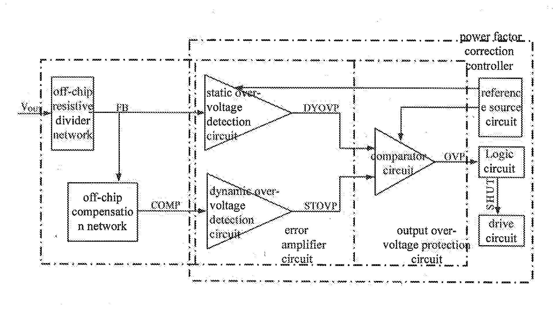
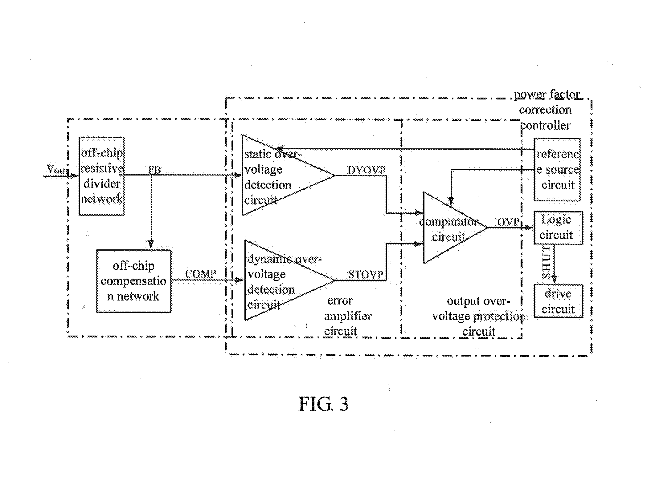
[0025]For convenience of description, the present invention provides a block diagram of the output over-voltage protection circuit used in power factor correction controller, which is shown in FIG. 3. The output over-voltage protection circuit of the present invention includes: an off-chip resistive divider network, an off-chip compensation network, a static over-voltage detection circuit, a dynamic over-voltage detection circuit, and a comparator circuit. The off-chip compensation network is coupled between the off-chip resistive divider network and the dynamic over-voltage detection circuit. The off-chip compensation network is configured to convert a dynamic over-voltage signal to a dynamic current signal and transmit the dynamic current signal to the dynamic over-voltage detection circuit. The dynamic over-voltage detection circuit is configured to detect the dynamic cur...


PUM


Abstract

An output over-voltage protection circuit for power factor correction, which includes a chip external compensation network, a chip external resistor divider network, a static over-voltage detection circuit, a dynamic over-voltage detection circuit and a compare circuit; The chip external compensation network is connected between the chip external resistor divider network and the dynamic over-voltage detection circuit, the chip external compensation network converts the dynamic over-voltage signal conversion to the dynamic current signal and conveys it to the dynamic over-voltage detection circuit, the dynamic over-voltage detection circuit detects the dynamic current signal and ultimately produces the dynamic over-voltage signal (DYOVP); The dynamic over-voltage signal (DYOVP) is inputted into the compare circuit, which converts the dynamic over-voltage signal (DYOVP) into a voltage compared with a reference voltage and outputs a over-voltage control signal (OVP), so as to achieve a dynamic over-voltage protection function.

Description

FIELD OF THE INVENTION[0001]The present invention relates to a field of electronic circuit technology, which also relates to analog integrated circuits, and more particularly relates to an output over-voltage protection circuit for power factor correction, which is applied to the output over-voltage protection in the power factor correction controller.BACKGROUND OF THE INVENTION[0002]Switching mode power supply with alternating current input is a typical electronic system, which has a wide range of applications, and a number of the switching mode power supply applied in the application is great. Most of the input rectifier filter in the internal thereof consists of uncontrolled rectifier circuits and capacitor filter circuits composed of diodes. Due to this, the problems of harmonic pollution and lower power factor of the switching mode power supply are generated. In order to improve the efficiency of the switching mode power supply and reduce the grid pollution, the power factor co...

Claims


Application Information

Patent Timeline
Patent Type & Authority Applications(United States)
IPC IPC(8): H02H9/04
CPCH02H9/04H02M1/32H02M1/42H02H7/125Y02B70/10Y02P80/10
Inventor DAI, GUODINGMA, XIAOHUIXUE, CHAOYAOOU, JIANLU, JING
Owner CSMC TECH FAB2 CO LTD
Why Eureka
Try Eureka